
Systems and methods for time corrected lightning detection

a technology of time-corrected lightning and detection methods, applied in direction finders, magnetic recording, atmospheric potential difference measurement, etc., can solve the problems of unsatisfactory adversely affecting the accuracy of return stroke estimated peak current estimates, and inability to accurately estimate the location of the return stroke and the estimated peak current of the stroke, etc., to achieve the effect of facilitating access to suitable time correction and speeding up throughpu

Inactive Publication Date: 2008-12-02
VAISALA
View PDF11 Cites 12 Cited by
  • Summary
  • Abstract
  • Description
  • Claims
  • Application Information

AI Technical Summary

Benefits of technology

The method significantly improves the accuracy of lightning strike location and current estimates, reducing uncertainties and enhancing the precision of lightning detection systems for various applications.

Problems solved by technology

If the conductivity of the terrain is not uniform with distance and bearing to the sensor, inaccurate estimates of amplitude at the location the lightning return stroke occurred will result from use of a smooth ellipsoid, uniformly conducting model of the earth's surface.
Distance, path length, and conductivity, as discussed above, modify (e.g., degrade, reshape, attenuate, or in some cases partially boost) the received signal amplitude in a complex manner and adversely affect the accuracy of estimates of the peak current of the return stroke.
For conventional lightning detection systems, the accuracy of the estimated location of the return stroke and estimated peak current of the stroke is unsatisfactory for many applications.

Method used


Image

  • Systems and methods for time corrected lightning detection
  • Systems and methods for time corrected lightning detection
  • Systems and methods for time corrected lightning detection

Examples


Embodiment Construction

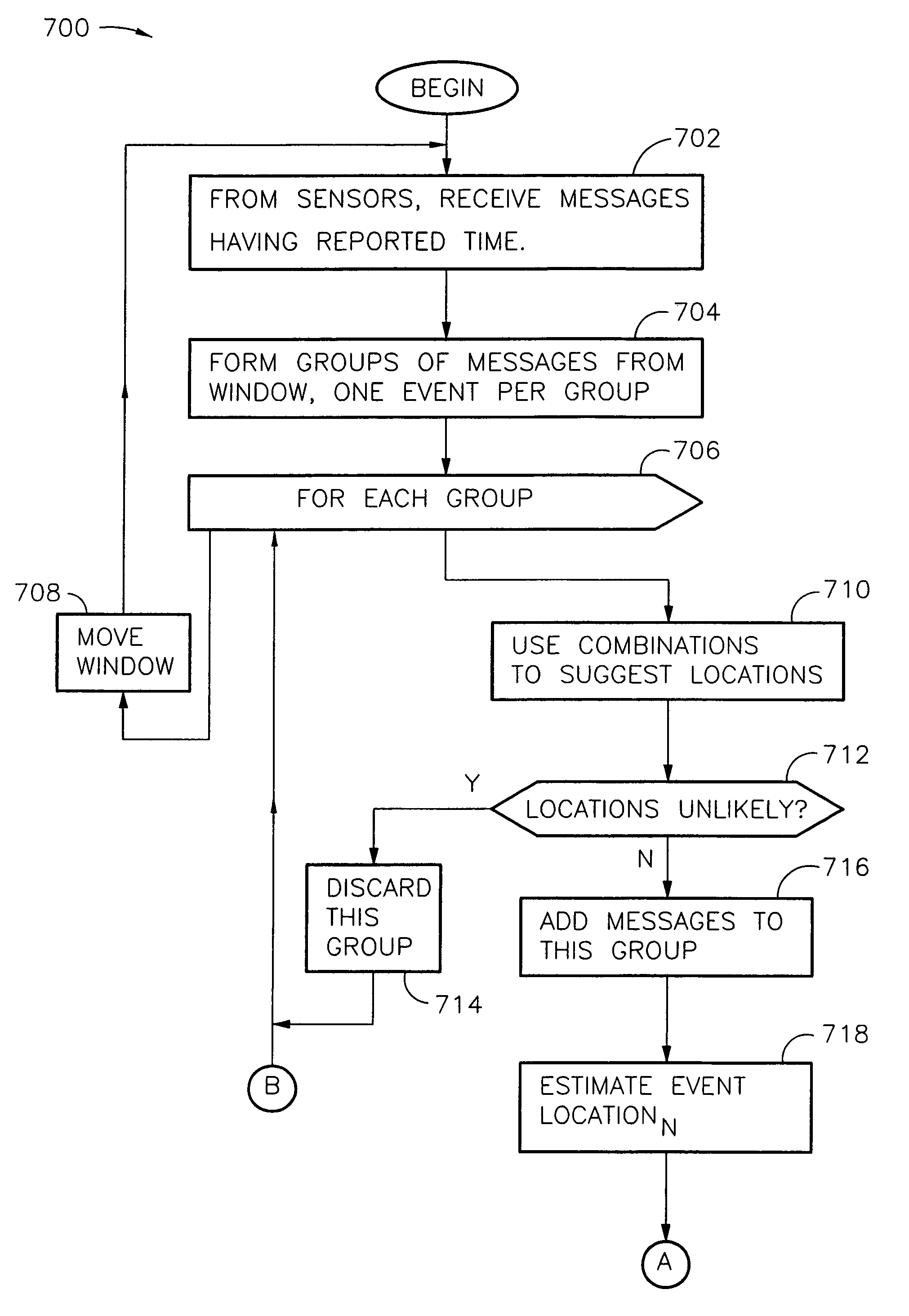
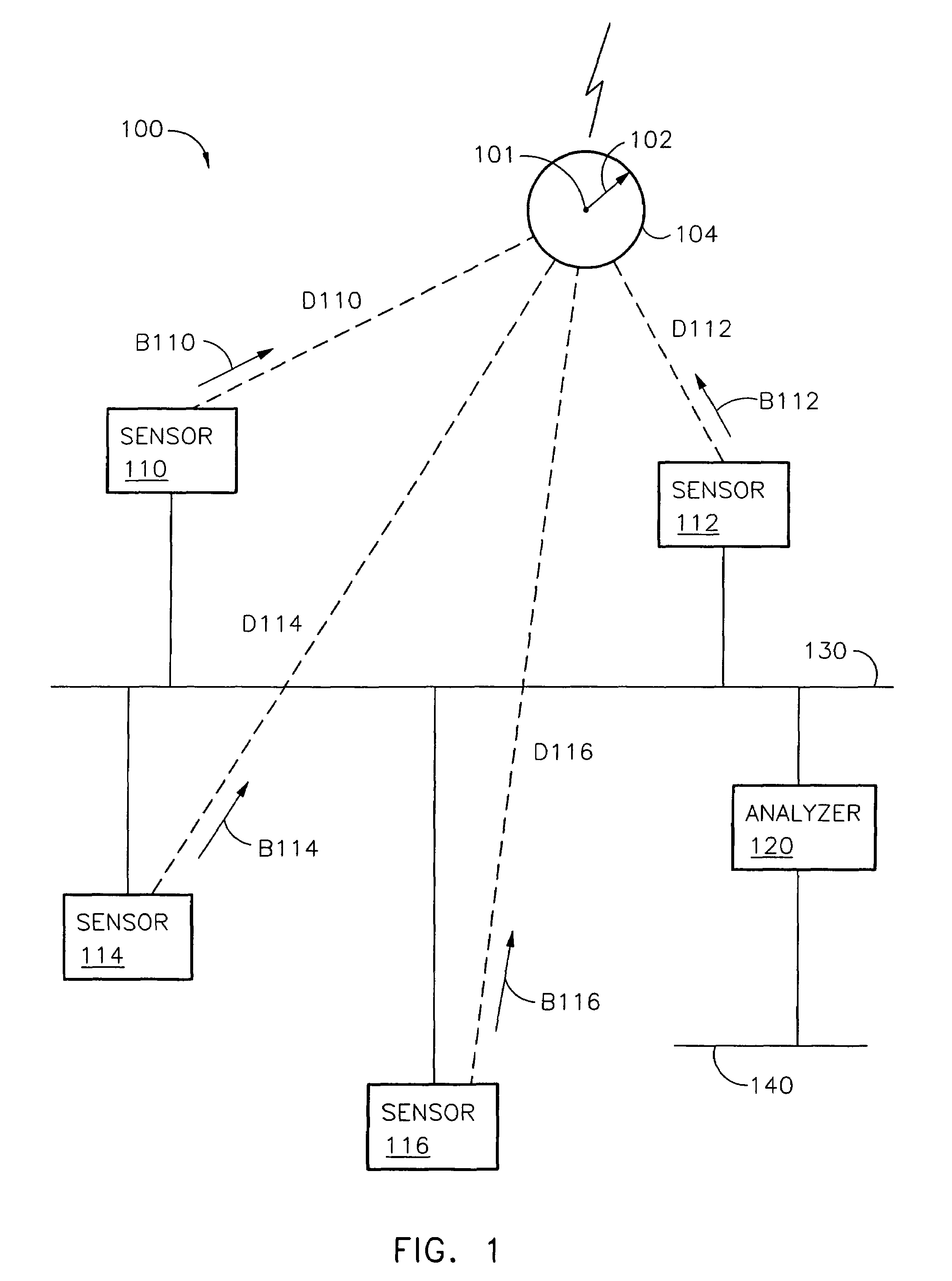
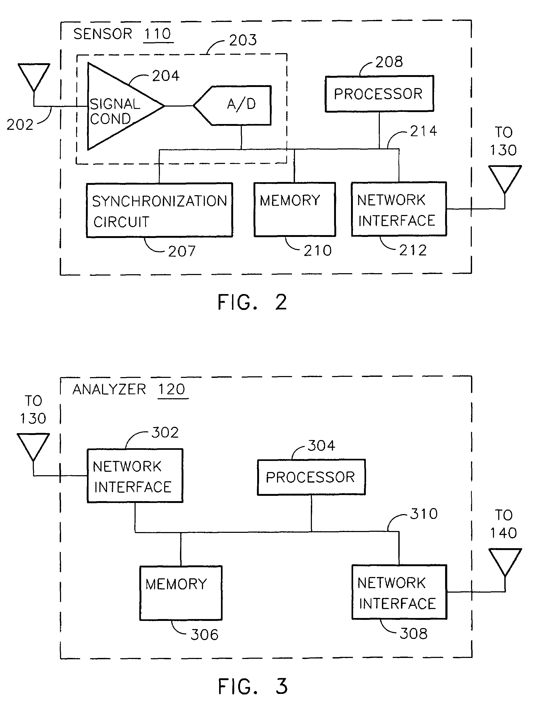
[0023]A lightning detection system, according to various aspects of the present invention estimates the location where each cloud to ground return stroke occurred at the ground. In alternate embodiments, the current of each return stroke is also estimated. Estimates are efficiently computed based on data collected by sensors which report to an analyzer. The analyzer receives sensor reports, computes estimated locations and currents, and reports (e.g., continuously) the occurrences of return strokes with estimates of respective location and current that are more accurate than conventional systems. Improved accuracy is due in part to using time corrections and / or amplitude corrections to supplement data from sensor reports. Time corrections and amplitude corrections, according to various aspects of the present invention, account for terrain (e.g., path length over mountainous terrain and / or nonuniform conductivity of the earth due to variation in terrain).

[0024]When radio signals prop...


PUM


Abstract

A lightning detection system provides an estimated location of a lightning stroke. The system includes sensors, and an analyzer. Each sensor provides messages having sensor identification, an amplitude responsive to the lightning stroke, and a time of detecting the lightning stroke. The analyzer applies time corrections and amplitude corrections to improve the accuracy of determining the location of the lightning stroke. Time adjustments and amplitude adjustments for the time and amplitude corrections are recalled from a matrix accessed according to a suggested or estimated location. The matrix may be organized by coordinates of longitude and latitude.

Description

CROSS REFERENCE TO RELATED APPLICATION[0001]This application is a continuation of and claims priority from U.S. patent application Ser. No. 10 / 395,809, filed Mar. 24, 2003, now U.S. Pat. No. 6,868,339 by inventors Martin Murphy, Wolfgang Schulz, Alburt Pifer, and Kenneth Cummins, which is incorporated herein by reference.FIELD OF THE INVENTION[0002]Embodiments of the present invention relate to systems and methods for estimating where lightning struck the ground. Other embodiments further relate to systems and methods for estimating the intensity of each lightning strike.BACKGROUND OF THE INVENTION[0003]A conventional low frequency wide-area lightning detection system detects and locates the return strokes in cloud-to-ground lightning flashes. Although the energy of each return stroke is emitted in a substantially vertical column between cloud and ground, the location of interest for each stroke is the point where the return stroke made contact with the ground. Wide-area lightning d...

Claims


Application Information

Patent Timeline
Patent Type & Authority Patents(United States)
IPC IPC(8): G01W1/00G06F19/00G01W1/16
CPCG01W1/16
Inventor MURPHY, MARTIN J.SCHULZ, WOLFGANGPIFER, ALBURT E.CUMMINS, KENNETH L.
Owner VAISALA
Learn More