Window fog detecting apparatus
a fog detection and window glass technology, applied in the direction of instruments, using mechanical means, material analysis, etc., can solve the problems of cumbersome determination of sensor installation portions, fog may occur at other parts of the window glass, and the reduction of the effect of compressor power and ventilation heat loss cannot be sufficiently achieved, so as to reduce reflection light, reduce projection light, and restrict the effect of contamination of the window glass 12
- Summary
- Abstract
- Description
- Claims
- Application Information
AI Technical Summary
Benefits of technology
Problems solved by technology
Method used
Image
Examples
first embodiment
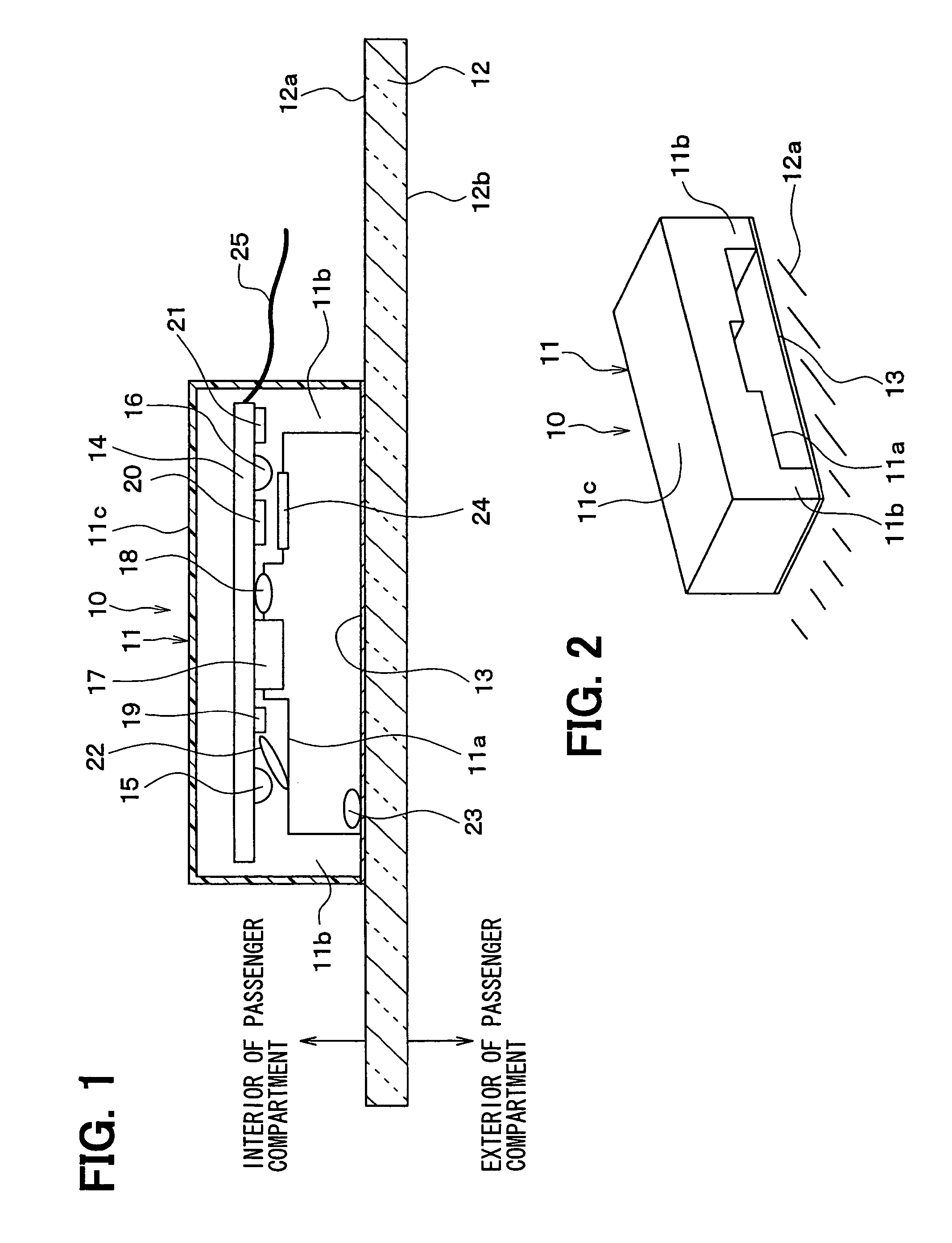
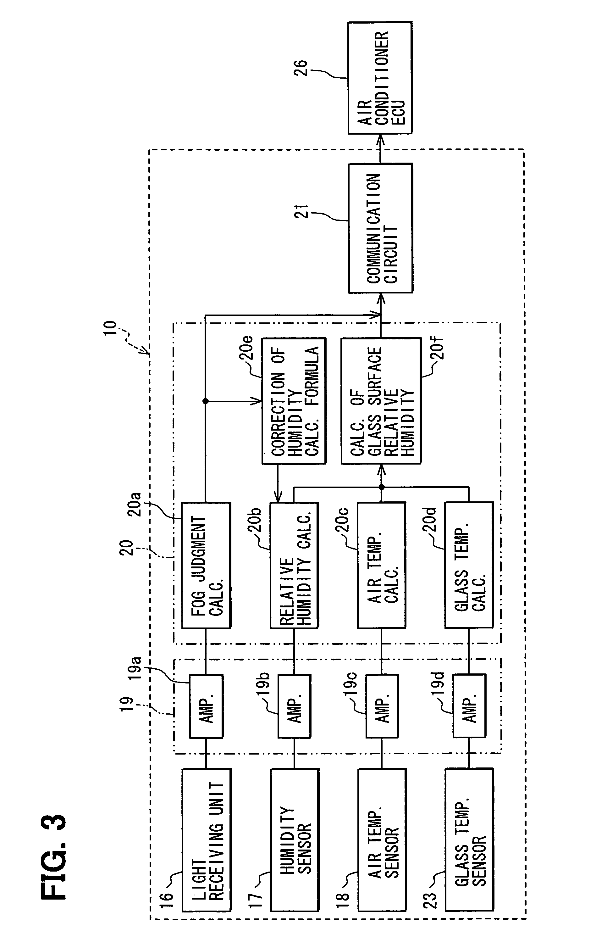
[0034]A window fog detecting apparatus 10 according to a first embodiment of the present invention will be described with reference to FIGS. 1-14. The window fog detecting apparatus 10 can be suitably used for an air conditioner for a vehicle, for example.
[0035]As shown in FIGS. 1 and 2, the window fog detecting apparatus 10 is provided with a case unit 11 made of a resin, for example. The case unit 11 has a substantially rectangular parallelepiped shape with a small height. The case unit 11 has a substantially convex-shaped opening portion 11a which is opened at a front wall portion and a back wall portion of the case unit 11. The lower portion (bottom portion) of the case unit 11 is completely opened.
[0036]The interior space of the case unit 11 is currently communicated with a peripheral space (e.g., interior of passenger compartment of vehicle) of the case unit 11 through the opening portion 11a which penetrates the front wall portion and the back wall portion of the case unit 11...
second embodiment
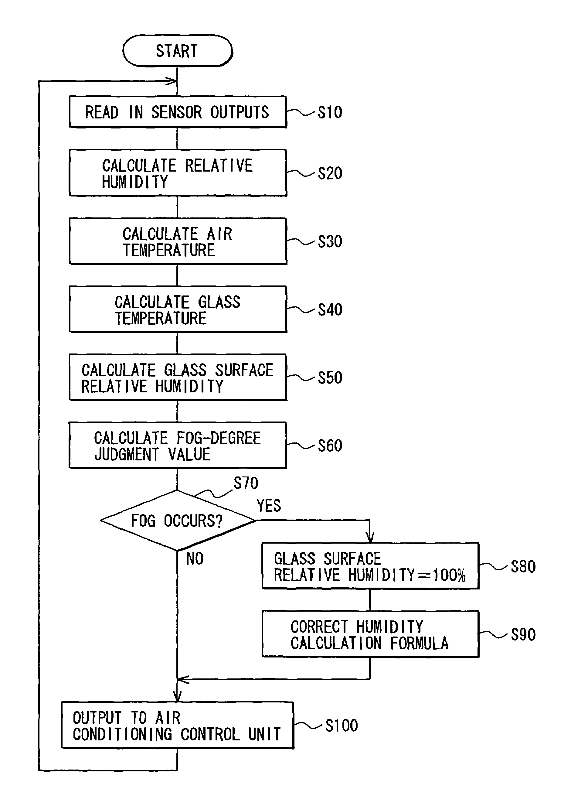
[0137]In the above-descried first embodiment, the correction of the humidity calculation formula is described. In this case, the calculated output value of the humidity sensor 17 deviates from the actual humidity to the lower humidity value side, so that fog occurs at the window glass 12 although the anti-fog control is performed by the vehicle air conditioner.
[0138]According to a second embodiment of the present invention, the humidity calculation formula is corrected in the case where the calculated output value of the humidity sensor 17 deviates from the actual humidity to a higher humidity value side.
[0139]In the case where the calculated output value of the humidity sensor 17 deviates from the actual humidity to the higher humidity value side, the effect of the anti-fog control operation by the air conditioner can be ensured. However, this may cause a problem that the inside air ratio is unnecessarily lowered and the ventilation heat loss is increased. Moreover, the capability ...
third embodiment
[0145]In the above-described second embodiment, the correction method in the case where fog occurs due to the manual operation of the passenger is provided. According to a third embodiment of the present invention, a similar correction can be carried out when a heating operation is started up at a low temperature.
[0146]In the case where the outside air temperature is low, for example, in winter, a temperature of the engine cooling water is lowered when the vehicle is parked (that is, engine is stopped). Therefore, a warming-up control may be performed. That is, when the air conditioner is started at the subsequent actuation of the engine, conditioned air is not blown out until the temperature of the engine cooling water becomes higher than or equal to a predetermined value.
[0147]Because conditioned air is not blown out in the warming-up control, fog may occur during the warming-up control so that the humidity calculation formula can be corrected.
[0148]In the case where fog occurs at...
PUM
| Property | Measurement | Unit |
|---|---|---|
| dielectric constant | aaaaa | aaaaa |
| temperature | aaaaa | aaaaa |
| temperature | aaaaa | aaaaa |
Abstract
Description
Claims
Application Information
 - R&D
- Intellectual Property
- Life Sciences
- Materials
- Tech Scout
- Unparalleled Data Quality
- Higher Quality Content
- 60% Fewer Hallucinations
Browse by: Latest US Patents, China's latest patents, Technical Efficacy Thesaurus, Application Domain, Technology Topic, Popular Technical Reports.
© 2025 PatSnap. All rights reserved.Legal|Privacy policy|Modern Slavery Act Transparency Statement|Sitemap|About US| Contact US: help@patsnap.com


