Heat exchanger

a heat exchanger and heat exchange medium technology, applied in the field of heat exchangers, can solve the problems of difficult selective change of supply orders and unreliability of control, and achieve the effect of uniform distribution of heat exchange medium and minimization of temperature variation

Inactive Publication Date: 2008-12-09
HANON SYST
View PDF13 Cites 13 Cited by
  • Summary
  • Abstract
  • Description
  • Claims
  • Application Information

AI Technical Summary

Benefits of technology

[0015]The present invention has been made to solve the foregoing problems and it is therefore an object of the present invention to provide a heat exchanger capable of selectively adjusting or opening / closing the flow of heat exchange medium therein to properly control heating or cooling capacity, minimize temperature variation, and uniformly distribute heat exchange medium through the same.
[0016]It is another object of the present invention to provide a heat exchanger in which distribution holes communicating with tubes, which are grouped by specific numbers, are sized in proportion to the number of the corresponding tubes to uniformly maintain the quantity and the flow rate of heat exchange medium flowing toward the tubes, thereby preventing lateral temperature difference and improving heat exchange performance.

Problems solved by technology

However, since the above scheme of controlling the heat exchange ability through the adjustment of air volume requires an additional apparatus, there is a problem in that control is not reliable.
Furthermore, in such heat exchanger system, it is not easy to selectively change a supplying order and position of heat exchange medium that is fed to the tubes.

Method used


Image

  • Heat exchanger
  • Heat exchanger
  • Heat exchanger

Examples


first embodiment

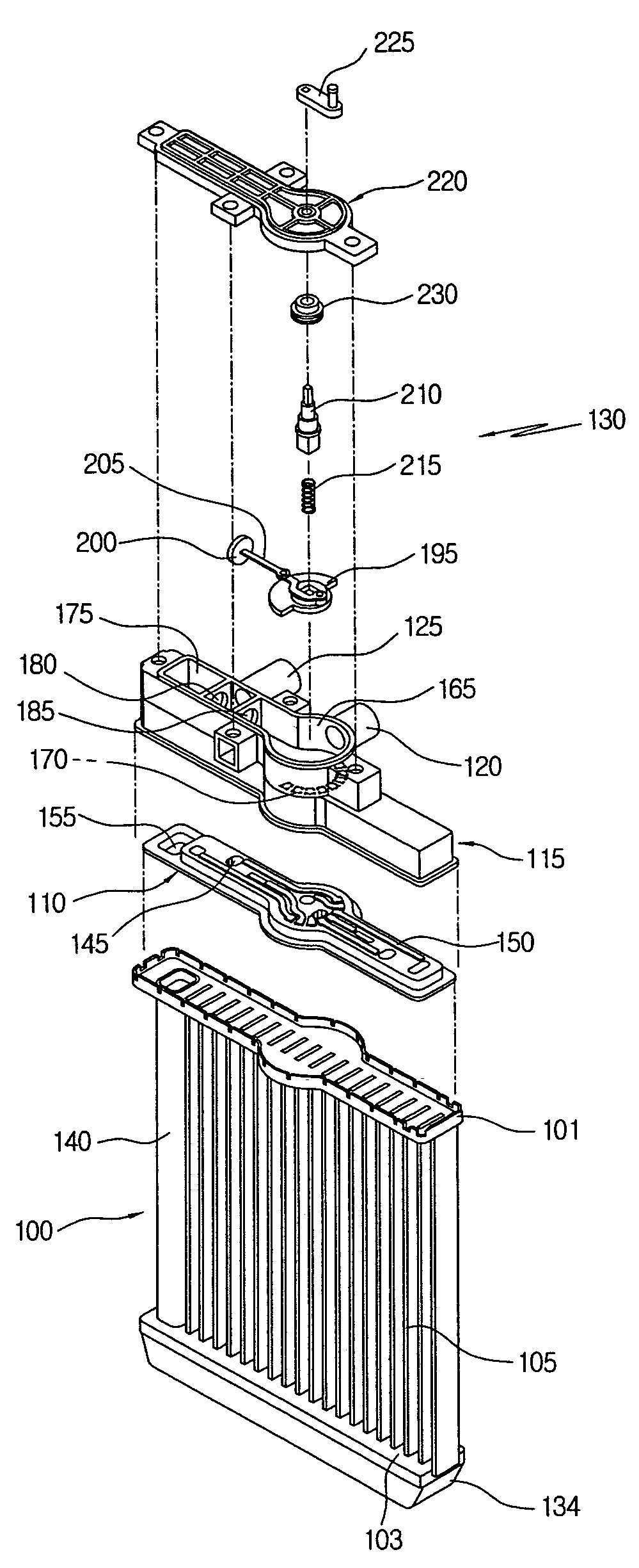
[0048]As shown in FIGS. 4 to 13, a heat exchanger 100 according to the present invention includes a plurality tubes 105 placed between upper and lower headers 101 and 103, in which each tube 105 has both ends fixed to the headers 101 and 103 and is designed to allows the passage of heat exchange medium therethrough, medium-distributing means 110 installed at the upper header 101 for feeding heat exchange medium to a specific one or all of the tubes 105, an upper tank 115 placed over the medium-distributing means 110. The upper tank 115 has a medium-inlet pipe 120 for feeding heat exchange medium, a medium-outlet pipe 125 for discharging heat exchange medium and distribution passages 190 formed therein for feeding heat exchange medium to specific regions of the medium-distributing means 110. The heat exchanger 100 also includes medium-regulating means 130 installed at the upper tank 115, which is automatically operated in response to a control signal to specify the quantity of heat e...

fourth embodiment

[0105]Accordingly, a heat exchanger 100 of the fourth embodiment includes a number of tubes 105 arranged at an interval, in which each of the tubes 105 has opened inlet and outlet 105a and 105 coupled with a header 101 and a U-shaped passage 150d formed therein to connect the inlet 105 with the outlet 105b, medium-distributing means 110 installed at the header 101 to feed heat exchange medium to a specific one or entire ones of the tubes 105 and a tank 115 installed at the header 101 to contain the medium-distributing means 110. The tank 115 has the medium-inlet pipe 120 for feeding heat exchange medium, a medium-outlet pipe 125 for discharging heat exchange medium and distribution passages 190 for feeding heat exchange medium to specific regions of the medium-distributing means 110. The heat exchanger 100 also includes medium-regulating means 130 installed inside the tank 115, in which the medium-regulating means 130 is automatically operated in response to a control signal to spec...

seventh embodiment

[0155]As shown in FIGS. 27 and 28, a heat exchanger 100 of the seventh embodiment includes tubes 105, in which each of the tubes has U-shaped passages 105d, which are vertically symmetrical with each other about thermal-insulating means 108, and inlets 105a and outlets 105b of the passages 105d formed in top and bottom ends and coupled with upper and lower headers 101. The heat exchanger 100 also includes upper and lower medium-distributing means 110 installed at the upper and lower headers 101, respectively, to feed heat exchange medium to specific ones or whole ones of the tubes 105, and upper and lower tanks 115 containing the upper and lower medium-distributing means 110, respectively, and coupled with the upper and lower headers 101, respectively. Each of the upper and lower tanks 115 has a medium-inlet pipe 120, a medium-outlet pipe 125 and a distribution passageway 190 for feeding heat exchange medium to a specific region of the medium-distributing means 110. In addition, the...


PUM


Abstract

The present invention relates to a heat exchanger which can suitably regulate the quantity, the feeding position or the feeding order of heat exchange medium fed into tubes to adjust heat exchange performance according to cooling and heating load. The heat exchanger comprises a plurality of tubes placed at least one header, each tube having both ends fixed to the header, medium-distributing means installed at the header for feeding heat exchange medium to the specific tubes, a tank placed over the medium-distributing means, the tank having a medium-inlet pipe, a medium-outlet pipe and distribution passages for feeding heat exchange medium to specific regions of the medium-distributing means, and medium-regulating means installed at the tank and operated in response to a control signal for adjusting the feed of the heat exchange medium.

Description

BACKGROUND OF THE PRESENT INVENTION[0001]1. Field of the Invention[0002]The present invention relates to a heat exchanger, in particular, which can suitably regulate the quantity of heat exchange medium fed into tubes to adjust heat exchange performance according to cooling and heating load. More particularly, the heat exchanger of the present invention can selectively regulate or open / close the flow of heat exchange medium therein to control heating or cooling capability, uniformly distribute heat exchange medium through the same, and uniformly maintain the quantity and flow rate of heat exchange medium flowing toward the tubes, thereby preventing lateral temperature difference as well as improving heat exchange performance.[0003]2. Background of the Related Art[0004]As well known in the art, an air conditioning system includes a cooling system and a heating system. In the cooling system, heat exchange medium discharged by the actuation of a compressor circulates through a condense...

Claims


Application Information

Patent Timeline
Patent Type & Authority Patents(United States)
IPC IPC(8): F28F27/00F28F27/02F28D1/053F28F9/02F28F9/22F28F13/06
CPCF28D1/05366F28F27/02F28F2250/06
Inventor HAN, SEONGSEOKPARK, TAEYOUNG
Owner HANON SYST
Why Eureka
Try Eureka