Flexible shoe assembly

a flexible, shoe technology, applied in the direction of application, bearing unit rigid support, manufacturing tools, etc., can solve the problems of excessive wear, poor wear resistance, and poor wear resistance of prior art devices, and achieve the effects of reducing localized wear and failure of wear pads, extending the life of wear pads, and reducing wear and early failure of wear pads

a flexible, shoe technology, applied in the direction of application, bearing unit rigid support, manufacturing tools, etc., can solve the problems of excessive wear, poor wear resistance, and poor wear resistance of prior art devices, and achieve the effects of reducing localized wear and failure of wear pads, extending the life of wear pads, and reducing wear and early failure of wear pads

US7461976B2Inactive Publication Date: 2008-12-09HUSKY INJECTION MOLDING SYST LTD

Image

  • Flexible shoe assembly
  • Flexible shoe assembly
  • Flexible shoe assembly

Examples


Embodiment Construction

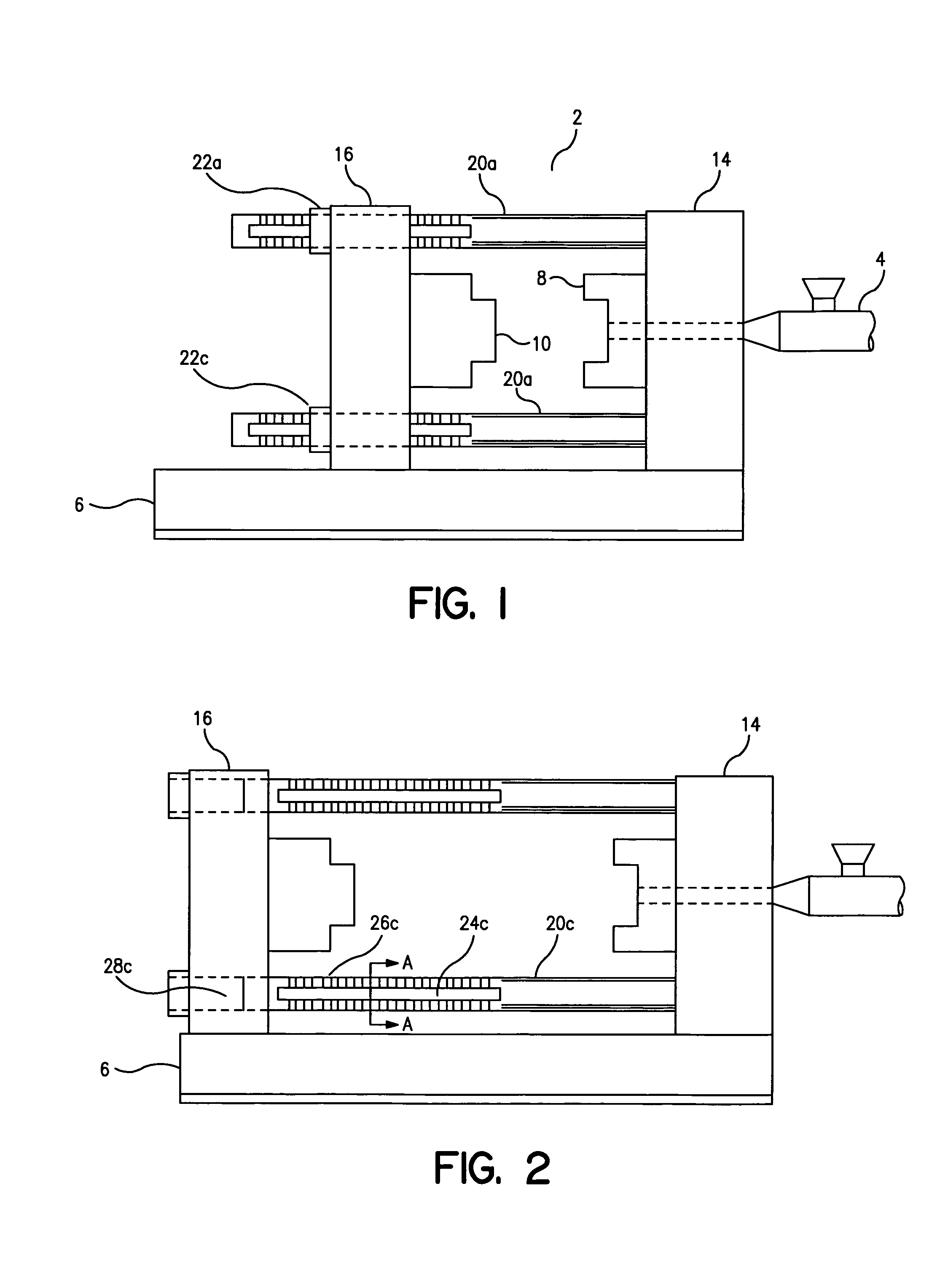
[0054]An embodiment of the present invention is described with initial reference to FIG. 1. The molding system includes a clamp unit 2 supported by a base 6 and an injection unit 4. The injection unit 4 provides for injecting a molten material, for example plastic, into a mold. Alternatively, the injection unit 4 provides for injecting a molten metal, for example a metal in a thixotropic state, into the mold. The injection unit 4 may also be omitted, for example with a blow mold system wherein a preform is introduced into a mold for subsequent shaping into a bottle.

[0055]The clamp unit includes a stationary platen 14 and a moving platen 16. Alternatively, the clamp unit may include more than one moving platen 16 in the case of a tandem machine. The moving platen 16 is movable quickly along the base 6 by a conventional mold stroke generator (not shown). The mold stroke generator may be hydraulic, electric, or a mechanical device to effectively open and close the mold.

[0056]The statio...


PUM

PropertyMeasurementUnit
heightaaaaaaaaaa
sizeaaaaaaaaaa
sizeaaaaaaaaaa

Abstract

A flexible shoe assembly for use in a molding system. The clamp unit of a molding system includes a moving platen and a stationary platen supported by a frame. Tie bars interconnect the moving platen with the stationary platen. The tie bars are secured to the stationary platen and pass through respective openings in the moving platen. Each tie bar is supported and guided within their respective openings by a flexible shoe assembly and wear pad. The flexible shoe assembly has a force redirector for directing force away from a peripheral edge of the wear pad towards a central force area. The flexible shoe assembly also includes a load distributor to distribute the load across the wear pad surface. The flexible shoe assembly includes an upper support that is flexible about a lower support to keep the wear pad in operational contact with the tie bar.

Description

[0001]This is a divisional of application Ser. No. 09 / 448,477, filed Nov. 24, 1999.FIELD OF THE INVENTION[0002]The present invention relates to industrial machines such as molding systems and more particularly, the invention relates to a dynamic shoe assembly for supporting and slideably guiding a horizontal tie bar member with a platen of a molding system.BACKGROUND OF THE INVENTION[0003]In the field of industrial machines having fixed and movable members, bushings, sleeves and shoe assemblies are well known and commonly used in industry.[0004]U.S. Pat. No. 5,624,695 entitled Securing Assembly For Injection Molding Machines issued on Apr. 29, 1997 to Husky Injection Molding Systems Ltd. and discloses a platen securing assembly. A stationary platen and moving platen are interconnected through a plurality of tie bar members. The tie bar members are supported and guided by a guide shoe located between the tie bar members and moving platen. The guide shoe is a fixed solid block of mate...

Claims


Application Information

Patent Timeline
09 Dec 2008
Publication
US7461976B2
IPC
F16C27/02; F16C29/00; B29C45/17; F16C29/02
CPC
B29C45/1761; F16C29/02; B29C2045/1764
Inventors
GLAESENER, PIERRE; KOLLMEIER, HARALD