Dazzle prevention device having electro magnetic wave detection function and detection mode selection

a technology of detection mode and detection plate, which is applied in the direction of optical radiation measurement, process and machine control, etc., can solve the problems of disturbing affecting the precise operation of the operator, and frequent operation of so as to reduce the light transmittance, prevent erroneous operation, and efficiently operate the dazzle prevention plate

Inactive Publication Date: 2008-12-09
OTOS TECH
View PDF7 Cites 5 Cited by
  • Summary
  • Abstract
  • Description
  • Claims
  • Application Information

AI Technical Summary

Benefits of technology

[0030]In accordance with the present invention, an electromagnetic wave detection and dazzle prevention device can determine the use of an electromagnetic wave detection means according to an environment, so that the electromagnetic wave detection means is not used when efficient control can be performed only by the optical detection means and the detection of an electromagnetic wave may cause erroneous operation, and the electromagnetic wave detection means can be additionally used according to the selection of the operator when efficient control cannot be performed only by the optical detection means, thus efficiently operating the dazzle prevention plate according to environmental conditions.
[0031]Furthermore, in accordance with the present invention, the electromagnetic detection sensitivity can be adjusted at the time of using the electromagnetic detection means, so that the detection of an electromagnetic wave generated in the environment of the operator can be minimized, thus preventing erroneous operation, such as an unnecessary reduction in light transmittance during work, and allowing the operator to perform precise operation.
[0032]Furthermore, the electromagnetic wave detection and dazzle prevention device can set priority so that an electromagnetic wave can be detected after light has been detected, so that the light transmittance of the dazzle prevention plate is reduced immediately after work has started thus allowing the operator to perform work after precisely identifying a welding or cutting area.

Problems solved by technology

However, in the case where only the optical detection means is used erroneous operation has occurred frequently due to the difference between detected signals, which may occur according to the type of welding or welding machine, and coherent light.
That is, in the case where only the optical detection means is used the light detection sensitivity increases at the time of low current welding, outdoor welding and thin plate welding, in which case there occurs erroneous operation in that the dazzle prevention plate 5 does not lighten or lightens excessively slowly notwithstanding that the dazzle prevention plate 5 mist lighten in response to surrounding coherent light.
However, the conventional dazzle prevention device equipped with the electromagnetic wave detection means is disadvantageous in that it is set to use the electromagnetic wave detection method regardless of environmental conditions, so that in an environment where plenty of electromagnetic waves are generated the light transmittance of the dazzle prevention plate is unnecessarily lowered during work based on electromagnetic waves generated in the environment other than the welding or cutting torch of the operator, thus disturbing the precise operation of the operator.
Furthermore, in the conventional dazzle prevention device equipped with the electromagnetic wave detection means, electromagnetic wave detection sensitivity is fixed so that electromagnetic waves, which are generated by sources other than the machine of the operator, such as an electromagnetic wave generated by the machine of some other operator, can be detected thus resulting in erroneous operation.
Furthermore, the conventional dazzle prevention device equipped with the electromagnetic wave detection means is disadvantageous in that although the operator must precisely identify a welding or cutting area before starting work, an electromagnetic wave is generated prior to light at the time of applying power to a welding or cutting machine or turning on a welding or cutting start switch because the optical detection means and the electromagnetic wave detection means are constructed to independently operate, so that light transmittance is lowered based on a detected electromagnetic wave even though light is not generated thus hindering the operator from performing work after identifying a precise welding or cutting area.

Method used


Image

  • Dazzle prevention device having electro magnetic wave detection function and detection mode selection
  • Dazzle prevention device having electro magnetic wave detection function and detection mode selection
  • Dazzle prevention device having electro magnetic wave detection function and detection mode selection

Examples


Embodiment Construction

[0040]Reference should now be made to the drawings, in which the same reference numerals are used throughout the different drawings to designate the same or similar components.

[0041]With reference to the accompanying drawings, the construction and operation of the present invention are described in detail.

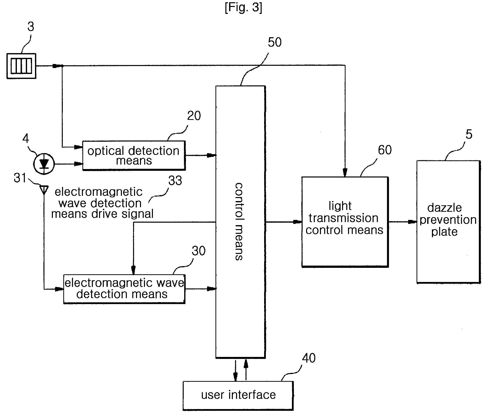
[0042]FIG. 3 is a block diagram showing an electromagnetic wave detection and dazzle prevention device according to the present invention. FIG. 4 is a circuit diagram showing the electromagnetic wave detection means 30 of the dazzle prevention device having an electromagnetic wave detection function according to the present invention.

[0043]As described in FIG. 3, the dazzle prevention device having an electromagnetic wave detection function according to the present invention includes an optical detection means 20, an electromagnetic wave detection means 30, a user interface 40, a control means 50 and a fight transmission control means 60.

[0044]The optical detection means 20 functio...


PUM


Abstract

A dazzle prevention device having an electromagnetic wave detection function is disclosed. The device includes an optical detection means, an electromagnetic wave sensor means, the electromagnetic wave detection means, a control means, and a light transmission control means. The optical detection means detects light generated from the welding or cutting torch. The electromagnetic wave sensor means detects an electromagnetic wave. The electromagnetic wave detection means compares a signal, which is input through the electromagnetic wave sensor means and resonated, with a variably set reference value. The control means applies the electromagnetic wave detection mean drive signal to the electromagnetic wave detection means and monitors the variation of an electromagnetic signal using the output of the electromagnetic wave detection means. The light transmission control means controls the variation of light transmittance of the dazzle prevention plate in response to an output signal from the control means.

Description

TECHNICAL FIELD[0001]The present invention relates, in general, to a dazzle prevention device having an electromagnetic wave detection function and, more particularly, to an dazzle prevention device having an electromagnetic wave detection function, which detects an electromagnetic wave generated along with high illuminance light at the time of welding or cutting and protects the eyes of an operator from dazzle.BACKGROUND ART[0002]Conventionally, in order to control the transmittance of light generated from a welding or cutting torch, a dazzle prevention device, which is worn on the head of an operator and equipped with an optical detection means, has been used.[0003]FIG. 1 is a perspective view showing a protective mask 1 equipped with a conventional dazzle prevention device 2.[0004]As shown in FIG. 1, the protective mask 1 provided with the dazzle prevention device on the front of the protective mask 1 reduces the illuminance of light, which is applied to the eyes of an operator, ...

Claims


Application Information

Patent Timeline
Patent Type & Authority Patents(United States)
IPC IPC(8): G01J1/32A61F9/06
CPCA61F9/067G02F1/13318
Inventor HUH, MOON YOUNG
Owner OTOS TECH
Why Eureka
Try Eureka