
Voltage controlled oscillator with temperature and process compensation

a voltage control and oscillator technology, applied in the field of oscillators, can solve the problems of increasing operating current and voltage, incurring undesirable cost inflation, etc., and achieve the effect of reducing fabrication costs

Inactive Publication Date: 2008-12-09
SUNPLUS TECH CO LTD
View PDF3 Cites 39 Cited by
  • Summary
  • Abstract
  • Description
  • Claims
  • Application Information

AI Technical Summary

Benefits of technology

[0009]In the light of the above descriptions, the present invention is directed to a voltage control oscillator, for resisting process fluctuation and temperature variance to the VCO, and reducing fabrication cost.

Problems solved by technology

Moreover, since fabrication fluctuation results in change of circuit states, the factors are all significant when designed to comply with specs and yield requirement.
In a conventional scheme, usually enlarging the circuit area, and increasing operating current and voltage incur undesirable cost inflation.

Method used


Image

  • Voltage controlled oscillator with temperature and process compensation
  • Voltage controlled oscillator with temperature and process compensation
  • Voltage controlled oscillator with temperature and process compensation

Examples


Embodiment Construction

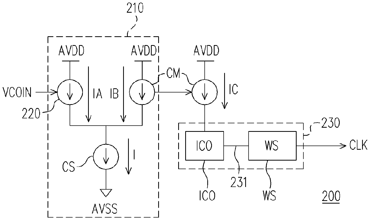
[0028]The circuit in the present invention comprises two parts: one part is positively correlated to the fabrication process or temperature; and the other part is negatively correlated to the fabrication process or temperature. By adjusting the variation rate of the factors of the two parts, the circuit can be controlled stable with the factors. When the current control oscillator CCO is supplied with a same current, if using SLOW fabrication process or higher temperature, the oscillating frequency is lower, whereas if using FAST fabricating process or lower temperature, the oscillating frequency is higher. Therefore, the voltage / current converter is designed to supply higher current under SLOW fabrication process or higher temperature, and to supply lower current under FAST fabrication process or lower temperature in the present invention. With a same input voltage VCOIN, the VCO generates a similar frequency, such that oscillating frequency is generated within designated range wit...


PUM


Abstract

A voltage control oscillator, outputting a clocking signal with a specific frequency according to an input voltage level, has a constant current source, a voltage / current converter, a current mirror and an oscillating circuit. The constant current source provides a predetermined reference current. The voltage / current converter is coupled to the constant current source, for determining a first current flowing through the voltage / current converter according to the input voltage. The current mirror has a first current terminal coupled to the constant current source, for determining a third current flowing through a second current terminal according to the second current flowing through the first current terminal, wherein the second current is the reference current subtracted by the first current. The oscillating circuit is coupled to the second current terminal of the current mirror, for determining a frequency of the clocking signal according to the third current.

Description

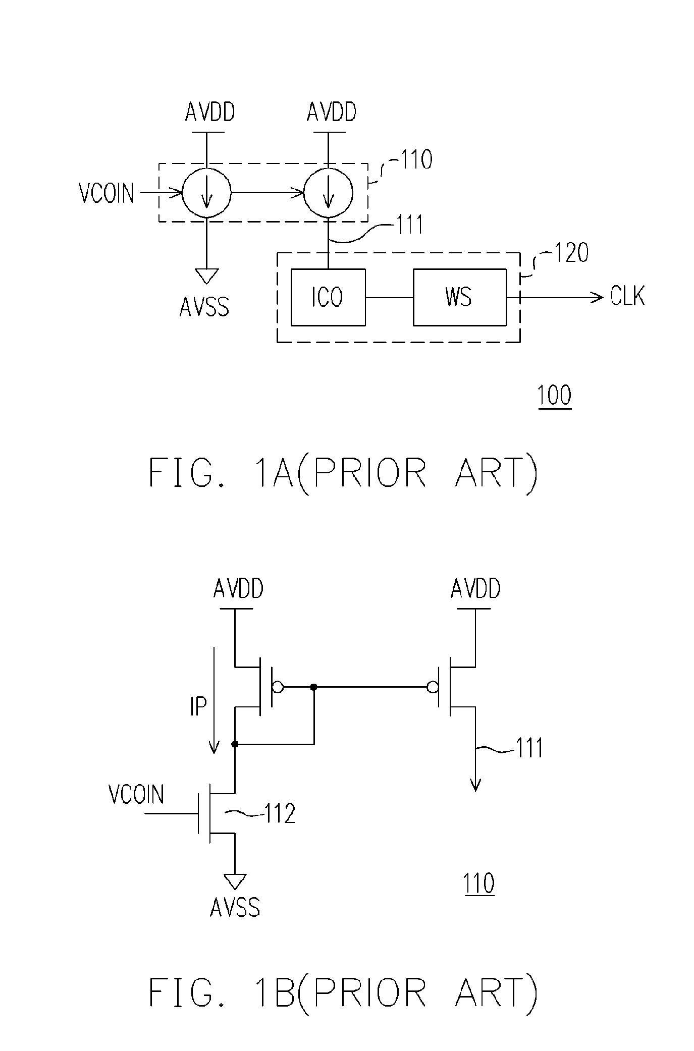
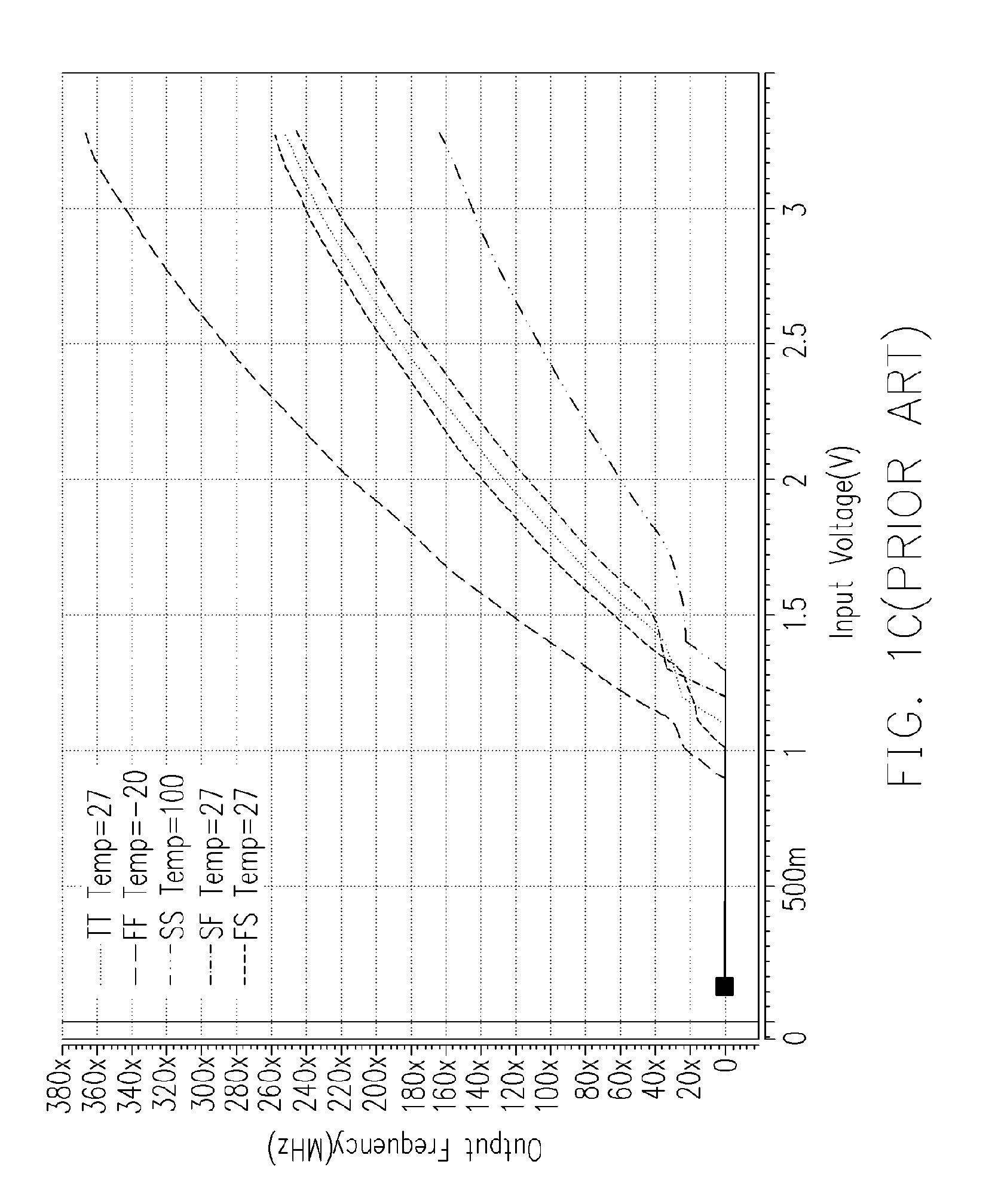
CROSS-REFERENCE TO RELATED APPLICATION[0001]This application claims the priority benefit of Taiwan application serial no. 93114371, filed May 21, 2004.BACKGROUND OF THE INVENTION[0002]1. Field of the Invention[0003]The present invention relates to an oscillator, and more particularly, to a voltage control oscillator.[0004]2. Description of Related Art[0005]A common VCO is illustrated as FIG. 1A. Referring to FIG. 1A, it is a schematic block diagram of a common VCO. In FIG. 1A, a clock signal CLK outputted from the VCO 100 is controlled by an input voltage VCOIN. The VCO 100 comprises a voltage / current converter 110 and a current control oscillating circuit 120. For the current control oscillating circuit 120, under a same supplying current 111, the oscillating frequency is lower if fabricated with SLOW process or operated in higher temperature, whereas the oscillating frequency is higher if fabricated with FAST process or operated in lower temperature.[0006]Referring to FIG. 1B, it ...

Claims


Application Information

Patent Timeline
Patent Type & Authority Patents(United States)
IPC IPC(8): H03K3/354H03B5/04H03L7/00H03L7/099
CPCH03L7/0995
Inventor TUNG, YEN-CHANG
Owner SUNPLUS TECH CO LTD
Learn More