Supercharge Your Innovation With Domain-Expert AI Agents!

Optical apparatus

a technology of optical equipment and optical lens, applied in the field of optical equipment, can solve the problems of small variation of image magnification caused by the motion of the focus lens (or the compensator), user discomfort, and difficulty in keeping the exit pupil of the image-picking optical system sufficiently far from an image plane, etc., to achieve high focusing performance and suppress the twitching of the image

Inactive Publication Date: 2008-12-09
CANON KK
View PDF4 Cites 0 Cited by
  • Summary
  • Abstract
  • Description
  • Claims
  • Application Information

AI Technical Summary

Benefits of technology

This solution effectively reduces image twitching and field angle variation, enabling high focusing performance and comfortable autofocus in non-telecentric optical systems, particularly in zoom lenses, by controlling the wobbling of lens units to maintain optimal image stability and clarity.

Problems solved by technology

When a back focus of an image-pickup optical system is shortened to reduce the size of the image-pickup optical system in response to a recent demand of miniaturization of the optical apparatus, it is difficult to keep an exit pupil of the image-pickup optical system sufficiently far from an image plane, so that the image-pickup optical system tends to become a non-telecentric optical system.
The minute wobbling in such an image-pickup optical system varies an image magnification, which causes a user to feel anomalous.
However, the optical system disclosed in Japanese Patent Laid-Open No. 6-205267 which is a rear-focus type is a near-telecentric optical system, so that the variation of the image magnification caused by the motion of the focus lens (or the compensator) is small.
Therefore, twitching of the image is almost unnoticeable even without causing the variator to wobble with the wobbling of the focus lens.
In contrast, in a zoom lens that is a non-telecentric optical system (that is, a zoom lens whose exit pupil position is varied with zooming), the wobbling of the focus lens (or the compensator) causes the image magnification to significantly vary, which may give discomfort to the user.

Method used


Image

  • Optical apparatus
  • Optical apparatus
  • Optical apparatus

Examples


embodiment 1

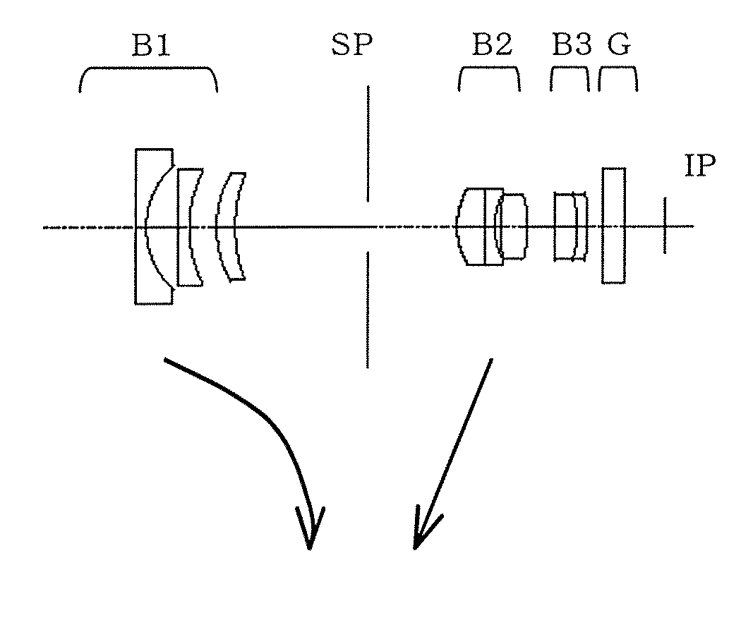
[0092]FIG. 3 shows a sectional view of the zoom lens (image-pickup optical system) at a wide-angle end, which is a first embodiment. The zoom lens has the optical configuration shown in TABLE 1.

[0093]

TABLE 1f = 3.52~6.47~8.88 Fno = 2.1~2.66~3.5 2ω = 65.2~38.4~28.4R1 = 500.00000D1 = 1.000N1 = 1.48749ν1 = 70.2R2 = 7.20738D2 = 2.743R3 = −179.53900D3 = 1.000N3 = 1.48749ν3 = 70.2R4 = 10.49384D4 = 2.370R5 = 9.29148D5 = 1.600N5 = 1.76182ν5 = 26.5R6 = 12.36689D6 = VARIABLER7 = APERTURE STOPD7 = VARIABLE*R8 = 6.23710D8 = 2.500N8 = 1.69350ν8 = 53.2R9 = ∞D9 = 0.800N9 = 1.69895ν9 = 30.1R10 = 6.16765D10 = 0.471R11 = 14.8436D11 = 2.4000N11 = 1.60311ν11 = 60.6R12 = −10.2412D12 = VARIABLER13 = 52.4000D13 = 2.000N13 = 1.69680ν13 = 55.5R14 = −8.6000D14 = 0.800N14 = 1.80518ν14 = 25.4R15 = −32.9000D15 = 1.400R16 = ∞D16 = 2.000N16 = 1.51633ν16 = 64.1R17 = ∞FOCAL LENGTHVARIABLE DISTANCE3.526.478.88D611.503.232.33D77.754.151.20 D122.406.008.95ASPHERIC COEFFICIENT*R8k = −6.27256e−01B = −1.46455e−04C = 3.29...

embodiment 2

[0128]Embodiment 1 used the voice coil motors (VCMs) as the first and second actuators 125 and 121 that drive the compensator 101 and variator 102. However, this embodiment uses stepping motors as the first and second actuators.

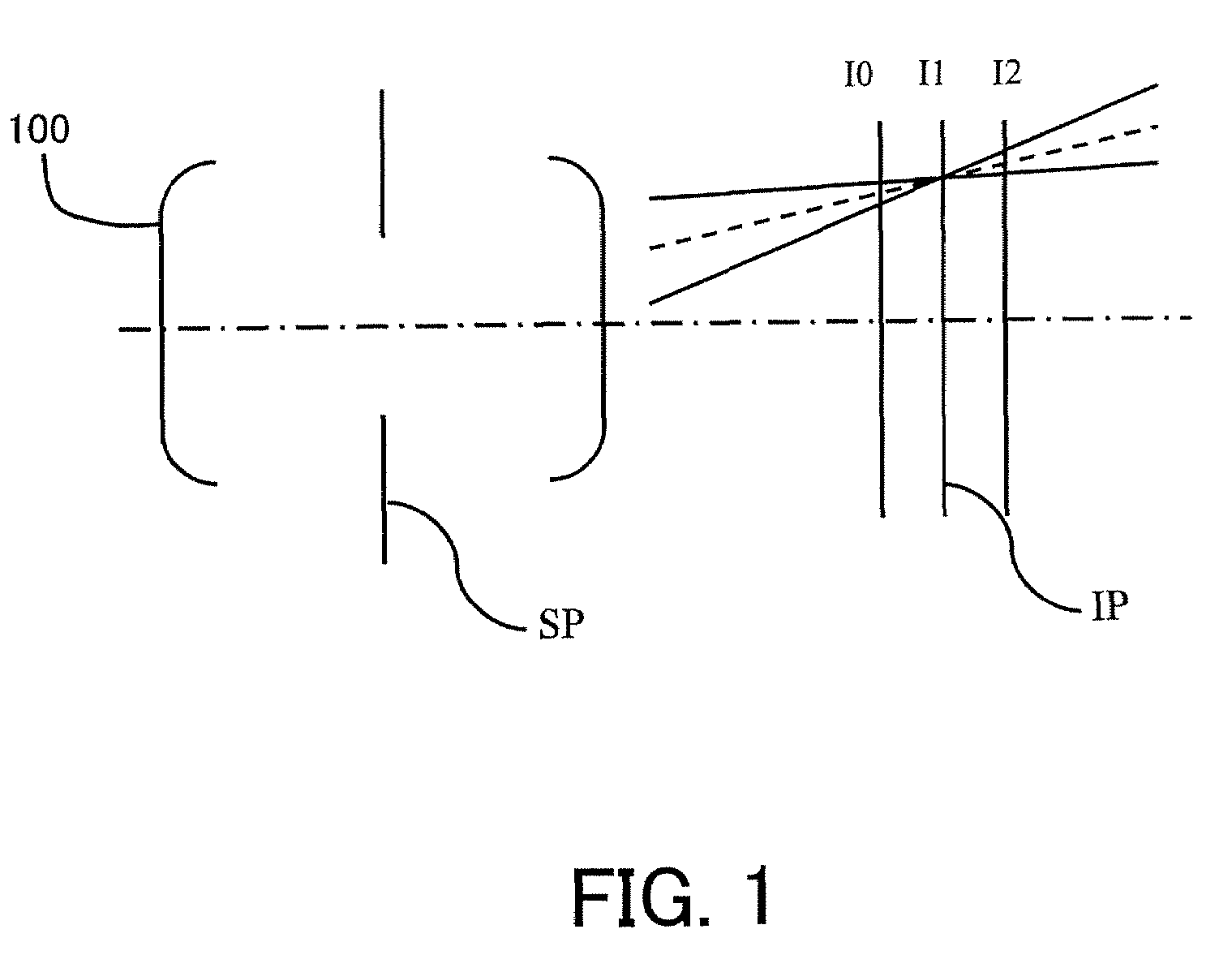
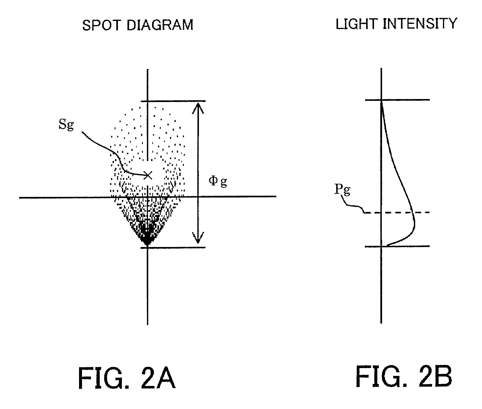
[0129]This embodiment also employs as an evaluation method of the image twitching and the field angle variation, the method using the movement of the light-intensity centroid Pg of the image out of focus by the predetermined amount.

[0130]Also in this embodiment, in order to reduce the movement of the light-intensity centroid Pg of the image out of focus (close to zero) when the compensator 101 is moved in the optical axis direction by 10 μm on the wide-angle side, the variator 102 is moved in the same direction as that of the compensator 101 by 4 μm. On the other hand, when the compensator 101 is moved in the optical axis direction by 10 μm on the telephoto side, the variator 102 is moved in the same direction as that of the compensator 101 by 6 μm.

[0131]Howe...

embodiment 3

[0132]FIG. 6 shows a sectional view of a vari-focal lens (image-pickup optical system) at a wide-angle end, which is a third embodiment. The vari-focal lens has the optical configuration shown in TABLE 2.

[0133]

TABLE 2f = 2.67~4.21~5.76 Fno = 1.4~1.4~1.4 2ω = 73.6~50.8~38.3R1 = 19.78209D1 = 0.900N1 = 1.64000ν1 = 60.2R2 = 8.26867D2 = 5.400R3 = −30.22480D3 = 0.900N3 = 1.64000ν3 = 60.2R4 = 10.33476D4 = 1.400R5 = 12.85371D5 = 2.200N5 = 1.84666ν5 = 23.8R6 = 24.84249D6 = VARIABLER7 = APERTURE STOPD7 = VARIABLE*R8 = 38.83714D8 = 1.700N8 = 1.78590ν8 = 43.9R9 = −21.07820D9 = 0.100R10 = 9.03651D10 = 2.500N10 = 1.69680ν10 = 55.5R11 = 19.64571D11 = 1.260R12 = −17.63970D12 = 1.800N12 = 1.80518ν12 = 25.5R13 = 8.85416D13 = 1.200R14 = 60.00000D14 = 2.200N14 = 1.69680ν14 = 55.5R15 = −12.50000D15 = 0.800R16 = 13.75000D16 = 4.200N16 = 1.51680ν16 = 64.2R17 = −11.20000D17 = VARIABLER18 = ∞D18 = 2N18 = 1.51680ν18 = 64.2R19 = ∞FOCAL LENGTHVARIABLE DISTANCE2.674.215.76D623.329.694.37D75.683.842.00 D172.003....


PUM


Abstract

An optical apparatus includes an optical system including first and second movable lens units independently movable in an optical axis direction, and a controller causing the first movable lens unit to wobble in the optical axis direction based on contrast information. The optical system satisfies |tk / L|<15, where tk represents a distance from an image plane position to an exit pupil position when the exit pupil position is closest to the image plane position, L represents an effective diagonal length of an image at the image plane position. The controller causes the second movable lens unit to wobble in the optical axis direction to reduce variation of the position of the exit pupil in association with the wobbling of the first movable lens unit. The apparatus is capable of suppressing image twitching while obtaining a high focusing performance.

Description

BACKGROUND OF THE INVENTION[0001]The present invention relates to an optical apparatus such as a digital still camera, a digital video camera and an interchangeable lens, and particularly to autofocusing (AF) control in the optical apparatus.[0002]Optical apparatuses using a solid-state image-pickup element often employ a so-called contrast AF (TV-AF) in which a focus lens (or a compensator) is moved by using contrast information generated from video signals to obtain an in-focus state.[0003]In addition, such optical apparatuses often employ a zoom optical system of an inner-focus type in which the focus lens (or the compensator) is driven when a variator that is a magnification-varying lens is moved while maintaining a certain optical positional relationship between the focus lens and the variator. Japanese Patent Laid-Open Nos. 4-134307 and 4-134308 disclose such an inner-focus type zoom optical apparatus.[0004]In the contrast AF, changes of the contrast value (value relating to t...

Claims


Application Information

Patent Timeline
Patent Type & Authority Patents(United States)
IPC IPC(8): G02B15/14
CPCG02B15/177G03B3/02G03B13/36G02B15/143
Inventor SAITO, SHINICHIRO
Owner CANON KK
Features
  • R&D
  • Intellectual Property
  • Life Sciences
  • Materials
  • Tech Scout
  • Unparalleled Data Quality
  • Higher Quality Content
  • 60% Fewer Hallucinations
Learn More