Method of fabricating inkjet nozzle chambers having filter structures

a filter structure and inkjet printing technology, applied in the field of inkjet printers, can solve the problems of nozzle failure, nozzle clog, ink contaminated, etc., and achieve the effect of preventing ink from leaking

Inactive Publication Date: 2008-12-16
SILVERBROOK RES PTY LTD +1
View PDF10 Cites 3 Cited by
  • Summary
  • Abstract
  • Description
  • Claims
  • Application Information

AI Technical Summary

Benefits of technology

[0017]Filtering the ink as it enters the chamber removes the contaminants and bubbles but it also retards ink flow into the chamber. The present invention uses a filter structure that has rows of obstructions in the flow path. The rows are offset with respect to each other to induce turbulence. This has a minimal effect on the nozzle refill rate but the air bubbles or other contaminants are likely to be retained by the obstructions.
[0058]Optionally, said photoresist is UV cured prior to deposition of said roof material, thereby preventing reflow of said photoresist during deposition.
[0086]Optionally, said photoresist is UV cured prior to deposition of said roof material, thereby preventing reflow of said photoresist during deposition.
[0109]Optionally, said photoresist is UV cured prior to deposition of said roof material, thereby preventing reflow of said photoresist during deposition.
[0125]Optionally, said wall projections are positioned for minimizing color-mixing of inks on said nozzle plate.

Problems solved by technology

Clogging is one of the principle causes of nozzle failure.
Nozzles can clog from dried ink and contaminants in the ink.
However, gas bubbles entrained in the ink flow are also seriously detrimental to nozzle operation.

Method used


Image

  • Method of fabricating inkjet nozzle chambers having filter structures
  • Method of fabricating inkjet nozzle chambers having filter structures
  • Method of fabricating inkjet nozzle chambers having filter structures

Examples


Embodiment Construction

[0192]In the description than follows, corresponding reference numerals relate to corresponding parts. For convenience, the features indicated by each reference numeral are listed below.

MNN MPN SERIES PARTS LIST

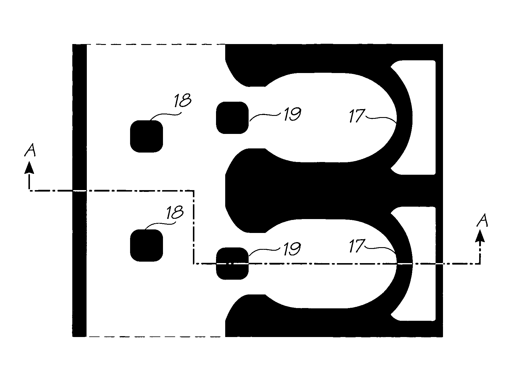
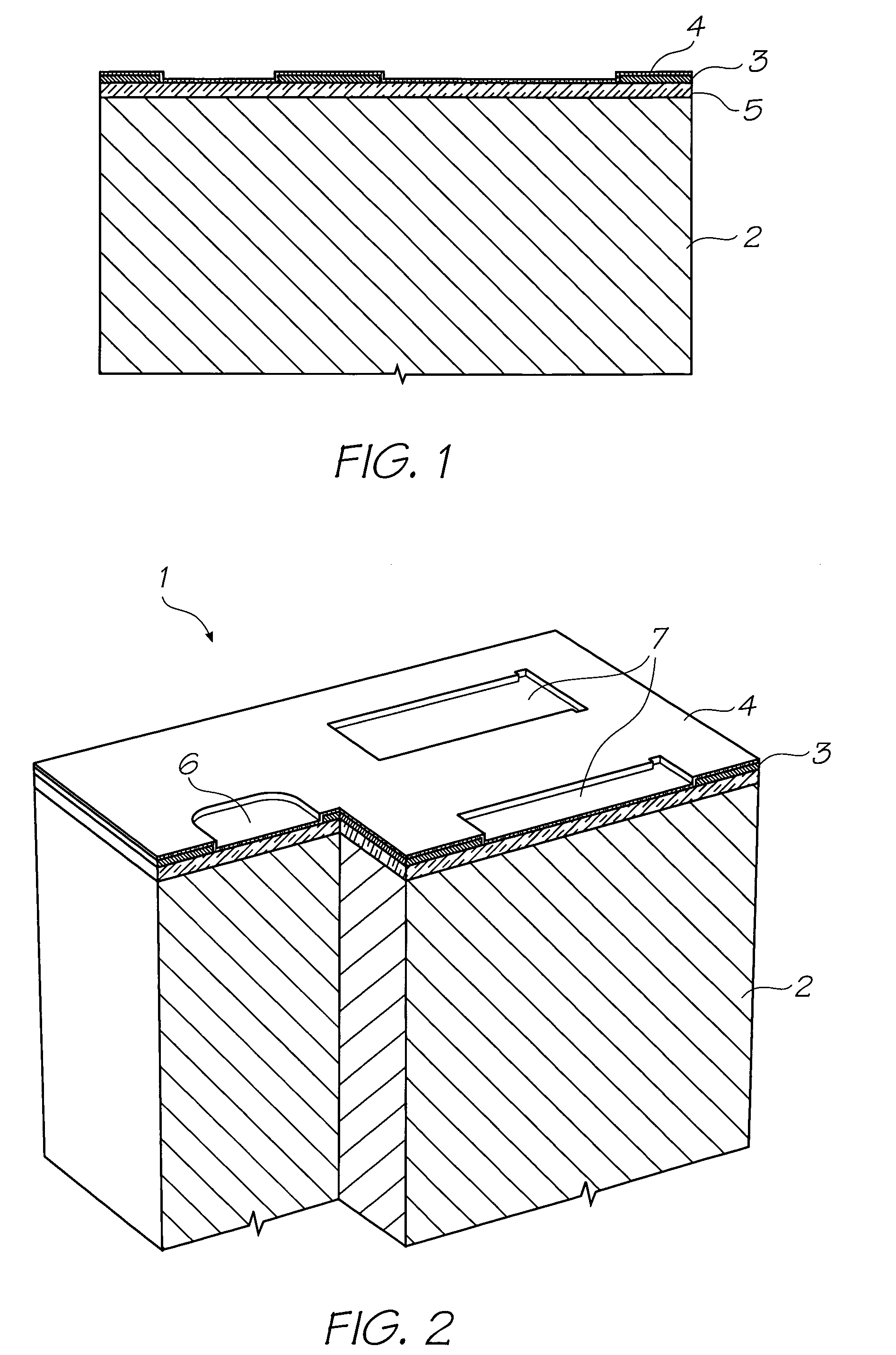
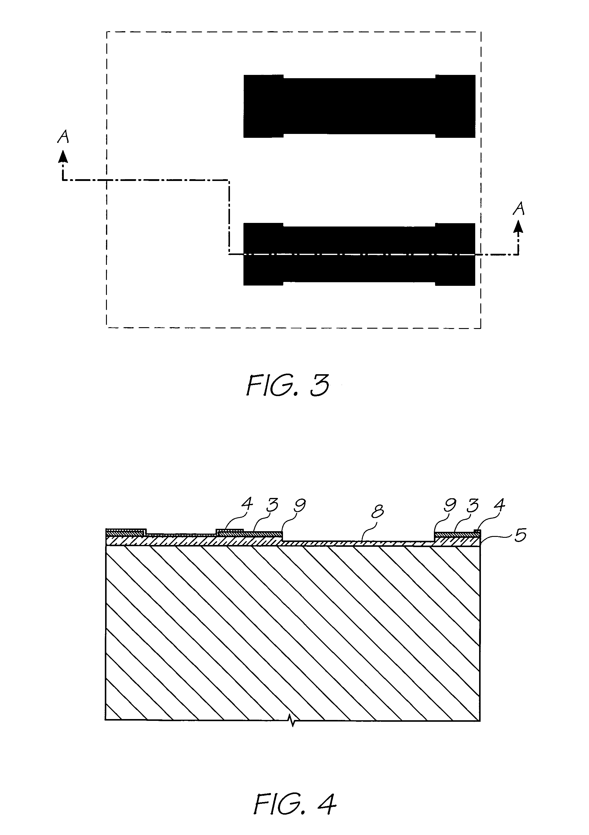
[0193]1. Nozzle Unit Cell[0194]2. Silicon Wafer[0195]3. Topmost Aluminium Metal Layer in the CMOS metal layers[0196]4. Passivation Layer[0197]5. CVD Oxide Layer[0198]6. Ink Inlet Opening in Topmost Aluminium Metal Layer 3.[0199]7. Pit Opening in Topmost Aluminium Metal Layer 3.[0200]8. Pit[0201]9. Electrodes[0202]10. SAC1 Photoresist Layer[0203]11. Heater Material (TiAlN)[0204]12. Thermal Actuator[0205]13. Photoresist Layer[0206]14. Ink Inlet Opening Etched Through Photo Resist Layer[0207]15. Ink Inlet Passage[0208]16. SAC2 Photoresist Layer[0209]17. Chamber Side Wall Openings[0210]18. Front Channel Priming Feature[0211]19. Barrier Formation at Ink Inlet[0212]20. Chamber Roof Layer[0213]21. Roof[0214]22. Sidewalls[0215]23. Ink Conduit[0216]24. Nozzle Chambers[0217]25. Ellipti...


PUM

PropertyMeasurementUnit
thicknessaaaaaaaaaa
thicknessaaaaaaaaaa
depthaaaaaaaaaa

Abstract

A method of fabricating a plurality of inkjet nozzles on a substrate. The method comprises the steps of: (a) providing a substrate having a plurality of trenches corresponding to ink inlets; (b) depositing sacrificial material so as fill the trenches and form a scaffold on the substrate; (c) defining openings in the sacrificial material; (d) depositing roof material over the sacrificial material to form nozzle chambers and filter structures simultaneously; (e) etching nozzle apertures through the roof material; and (f) removing the sacrificial material.

Description

FIELD OF THE INVENTION[0001]The present invention relates to the field of inkjet printers and discloses an inkjet printing system using printheads manufactured with micro-electromechanical systems (MEMS) techniques.CO-PENDING APPLICATIONS[0002]The following applications have been filed by the Applicant simultaneously with the present application:[0003]11 / 24667611 / 24667711 / 24667811 / 24667911 / 24668011 / 24668111 / 24671411 / 24671311 / 24668911 / 24667111 / 24667011 / 24666911 / 24670411 / 24671011 / 24668811 / 24671611 / 24671511 / 24670711 / 24670611 / 24670511 / 24670811 / 24669311 / 24669211 / 24669611 / 24669511 / 24669411 / 24668711 / 246718732268111 / 24668611 / 24670311 / 24669111 / 24671111 / 24669011 / 24671211 / 24671711 / 24670911 / 24670011 / 24670111 / 24670211 / 24666811 / 24669711 / 24669811 / 24669911 / 24667511 / 24667411 / 246667730393011 / 24667211 / 24668311 / 246682[0004]The disclosures of these co-pending applications are incorporated herein by reference.CROSS REFERENCES TO RELATED APPLICATIONS[0005]Various methods, systems and apparatus relating to...

Claims


Application Information

Patent Timeline
Patent Type & Authority Patents(United States)
IPC IPC(8): B21D53/76G01D15/00
CPCB41J2/1404B41J2/1433B41J2/162B41J2/1626B41J2/1628C23F4/00B41J2002/14403Y10T29/4913Y10T29/49401Y10T29/49153Y10T29/49135Y10T29/49133B41J2002/14475
Inventor SILVERBROOK, KIA
Owner SILVERBROOK RES PTY LTD
Why Eureka
Try Eureka