Operating an air-hybrid vehicle with camshaft-driven engine valves

a technology of engine valves and camshafts, applied in the field of vehicle systems, can solve the problems of high cost and complexity of electric hybrids, and achieve the effects of reducing the cost and complexity of air-hybrid systems, improving the reliability of air-hybrid systems, and reducing valve energy consumption

Inactive Publication Date: 2008-12-16
EXXON RES & ENG CO
View PDF4 Cites 27 Cited by
  • Summary
  • Abstract
  • Description
  • Claims
  • Application Information

AI Technical Summary

Benefits of technology

[0028]One object of the present invention is to reduce the cost and complexity of an air-hybrid system by developing a camshaft-based valve train suitable for operation in an air-hybrid engine. Camshaft-based valve train is simple and inexpensive, and using it instead of the complicated and costly electrohydraulic camless valve train achieves the stated objective.
[0029]Another object of the present invention is to improve the reliability of the air-hybrid system. This too is accomplished by replacing a camless valve train with a camshaft-based system. Camless valve train carries a risk of piston-to-valve collision, which can lead to engine failure. In a system using camshafts, such risk is almost non-existent.
[0030]Still another object of the present invention is to reduce consumption of energy for valve operation in an air-hybrid engine. Operating a camless electrohydraulic valve train involves conversion of engine mechanical energy into hydraulic energy, to drive the valves, and into electric energy, to operate the solenoid valves. This is an inefficient process that adversely affects the system efficiency. On the other hand, a camshaft is a relatively low friction device that requires very little of the engine energy for its operation. Thus, using a more energy-efficient camshaft-based valve train improves the energy consumption of the air hybrid.
[0031]A further object of the present invention is to facilitate conversion of fleets of existing conventional vehicles into air-hybrid v

Problems solved by technology

The cost and complexity of e

Method used


Image

  • Operating an air-hybrid vehicle with camshaft-driven engine valves
  • Operating an air-hybrid vehicle with camshaft-driven engine valves
  • Operating an air-hybrid vehicle with camshaft-driven engine valves

Examples


Embodiment Construction

FIGS. 1 to 9

[0053]A preferred embodiment of the present invention is illustrated in FIGS. 1 to 9.

1. The Engine

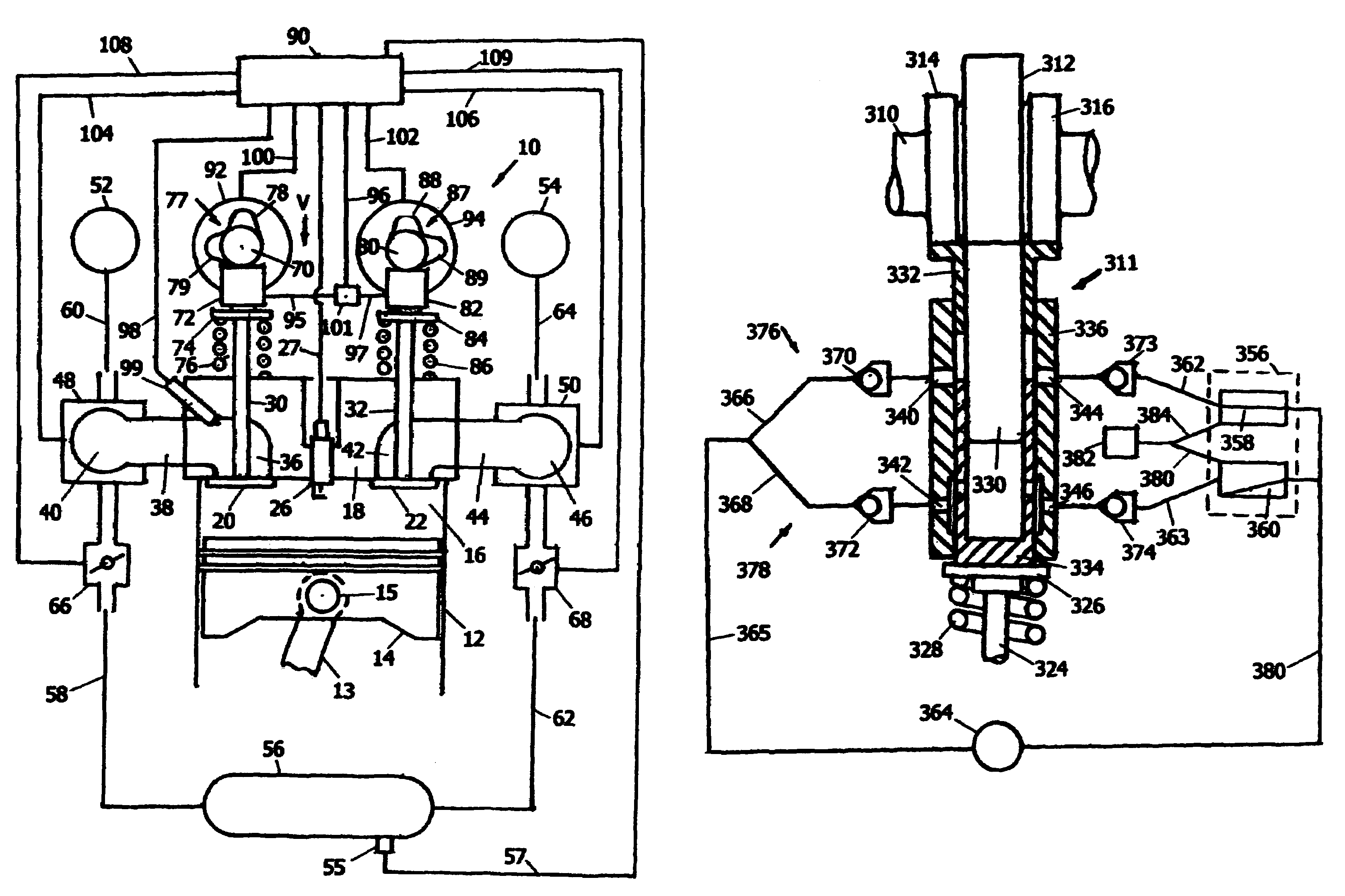
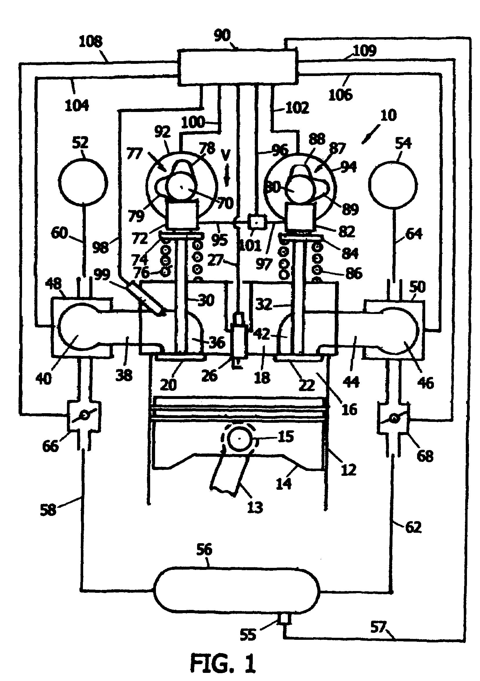
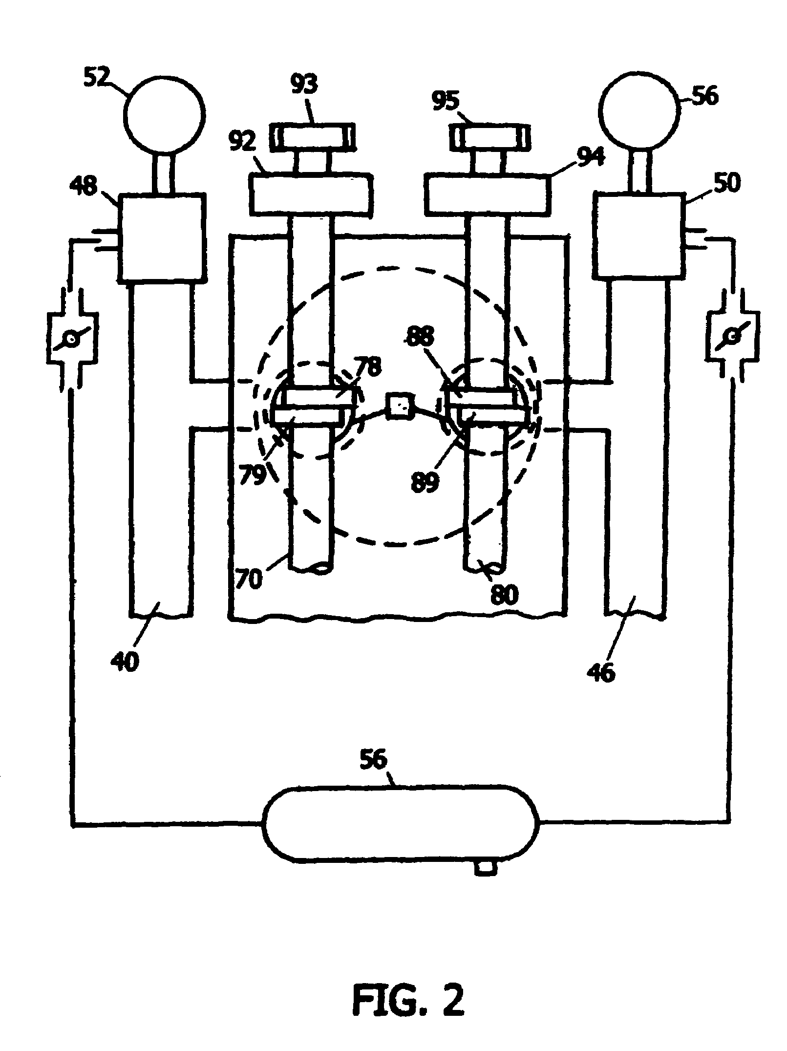
[0054]FIG. 1 is a schematic, cross-sectional side-view of an engine cylinder and head arrangement and its gas exchange system controlling the cylinder connection to outside atmosphere and to a compressed-air reservoir. FIG. 2 complements FIG. 1. It is a schematic, plane view of the same cylinder as seen looking in the direction of arrow V in FIG. 1. An engine 10 has at least one cylinder 12 containing a piston 14. Piston 14 is mounted upon a connecting rod 13 by a wrist pin 15 and can reciprocate in cylinder 12, thus varying the volume of a cylinder chamber 16 enclosed between piston 14 and a cylinder head 18 attached to the top of cylinder 12.

[0055]Two types of normally-closed valves, a first valve 20 and a second valve 22, are installed in cylinder head 18. Valves 20 and 22 are slideably mounted in guides 30 and 32, respectively, which are arranged in cylinder head 18. Dep...


PUM


Abstract

An air-hybrid engine operates in two operational modes. It employs uniquely designed camshafts with cam lobe activators, and camshaft phase shifters to operate and control the engine valves. It uses a different cam lobe for operating an engine valve during each of the two operational modes, and it uses camshaft phase shifters to vary the valve event timing and duration. The system exploits non-linearity that exists in relationship between the piston motion and the camshaft rotation. Varying the phase relationship between the camshaft and the engine crankshaft in a pre-determined specific way varies the duration of the engine valve opening in the required way, thus varying the volumes of air received into and discharged from the engine.

Description

CROSS-REFERENCE TO RELATED APPLICATIONS[0001]Application Ser. No. 10 / 822,448. Filing Date: Apr. 9, 2004FEDERALLY SPONSORED RESEARCH[0002]Not ApplicableSEQUENCE LISTING OR PROGRAM[0003]Not ApplicableFIELD OF THE INVENTION[0004]The present invention relates to vehicle systems capable to accumulate energy derived from vehicle motion during its deceleration or obtained from operation of the vehicle engine, and use the accumulated energy to assist in vehicle acceleration and propulsion at a later time.BACKGROUND OF THE INVENTION[0005]In most vehicles, their typical driving pattern involves frequent accelerations, each followed by a deceleration. Each acceleration involves a significant increase in fuel consumption needed to produce the additional energy necessary to increase the vehicle speed. Then, during a subsequent deceleration, this added energy is absorbed by vehicle brakes and dissipated as heat. Attempts to overcome such waste of energy led to development of systems in which the ...

Claims


Application Information

Patent Timeline
IPC IPC(8): F01L1/34
CPCB60K6/12F01B17/02F01L9/025F01L13/0036F02D13/0219F02D13/04F01L1/143F02B21/00F01L2001/34446Y02T10/6282Y02T10/6208F01L9/14Y02T10/62
Inventor SCHECHTER, MICHAEL MOSES
Owner EXXON RES & ENG CO
Why Eureka
Try Eureka