Hydraulic lash adjuster

a technology of lash adjuster and lash, which is applied in the direction of valve arrangement, machine/engine, mechanical equipment, etc., can solve the problems of lash adjuster leakage, low and a lower pressure in the high-pressure chamber

Inactive Publication Date: 2008-12-16
GM GLOBAL TECH OPERATIONS LLC
View PDF1 Cites 10 Cited by
  • Summary
  • Abstract
  • Description
  • Claims
  • Application Information

AI Technical Summary

Benefits of technology

[0006]The present invention provides an improved hydraulic lash adjuster that prevents the ingestion of air through the bore / plunger clearance into the high-pressure chamber. The improved hydraulic lash adjuster includes a seal arrangement at the bore / plunger clearance that prevents air leakage into the high-pressure chamber through the bore / plunger clearance while allowing oil flow out of the high-pressure chamber through the clearance as is necessary for proper lash adjuster leak-down. The present invention is also directed at maintaining a flow path that runs from the reservoir chamber through the check valve into the high-pressure chamber and out of the high-pressure chamber through the bore / plunger clearance, but not the opposite direction.
[0009]A plunger spring is disposed in the high pressure chamber. The plunger spring urges the plunger away from the closed end of the bore. In accordance with the invention, the plunger further includes a circumferential groove between the second oil inlet passage and an end of the plunger distal from the high pressure chamber for preventing leakage of air through the calibrated clearance into the high pressure chamber.
[0010]In a specific embodiment, the circumferential groove is configured to maintain a small reservoir of oil in the upper portion of the clearance to maintain an oil seal and prevent the passage of air downward through the clearance.

Problems solved by technology

These positions cause the valve springs to be compressed, providing reaction forces that result in lash adjuster leak-down.
After the engine has been shut off for a period of time, the engine oil galleries that feed oil to the hydraulic lash adjusters will drain and draw in air, often leaving an upper portion of the lash adjuster plunger exposed to air.
Further, upon cooling of the engine while not running, the pressure in the high-pressure chamber will slowly become lower than atmospheric pressure due to the contraction of oil in the chamber.
The slow contraction of the oil in the high-pressure chamber is not enough to open a check valve of the lash adjuster that is disposed between the high-pressure chamber and a reservoir chamber.
The slow contraction of the oil, however, is sufficient to draw oil into the high-pressure chamber from the clearance between the plunger and the bore.
In some valvetrain designs, there is not a sufficient supply of oil at the top portion of the clearance between the plunger and the bore to prevent air from also entering the clearance.
This return stroke of the plunger at restart takes place rapidly and results in a significantly lowered pressure in the high-pressure chamber.
Air in the high-pressure chamber of the lash adjuster then results in inadequate lash adjustment that produces an audible valvetrain noise.

Method used


Image

  • Hydraulic lash adjuster
  • Hydraulic lash adjuster
  • Hydraulic lash adjuster

Examples


first embodiment

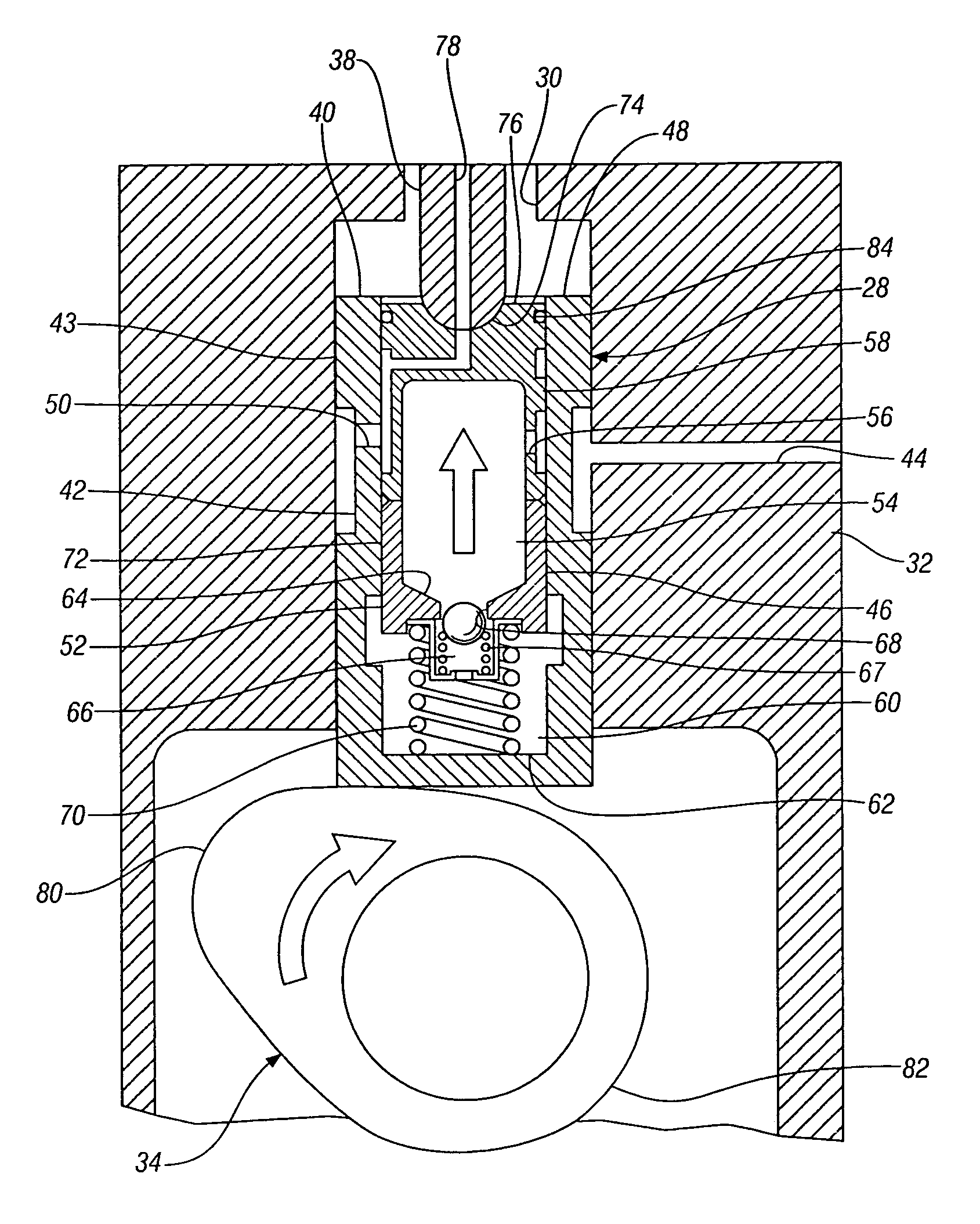
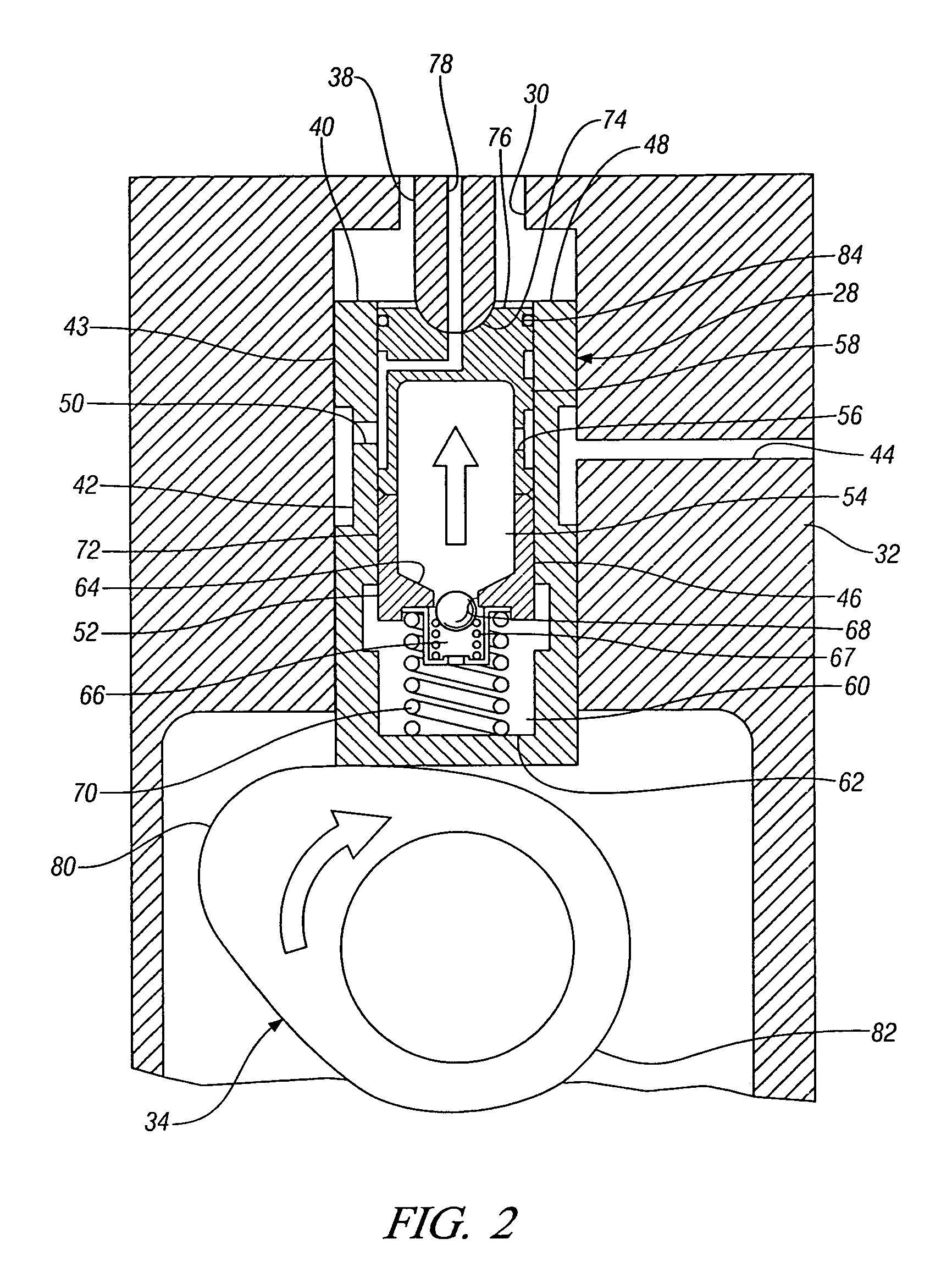
[0030]With reference now to FIGS. 2 through 4, the present invention provides a circumferential external groove 84 around the side wall 58 of the plunger 52, between the second oil inlet passage 56 and the distal end 76 of the plunger. The groove 84 is configured to restrict the passage of air through the plunger to body clearance 72 into the reservoir chamber 54. In a first embodiment, the circumferential groove 84 functions as a small reservoir that holds oil to maintain an oil seal in the clearance 72 that prevents flow of air into the high pressure chamber 60 through the clearance 72. The oil is held in the groove 84 by the oil's natural adhesion to metal and by the surface tension of the oil.

[0031]During engine off periods, the oil in the groove 84 is a source of oil to maintain the clearance seal when the distal end 76 portion of the plunger 52 is exposed to air (see for example FIG. 3). This prevents air from entering the high pressure chamber 60 during non-use of the engine....

second embodiment

[0032]Turning to FIGS. 5 through 7B, in the present invention, a seal ring 186 such as an expandable type ring may be disposed in the circumferential groove 184. The seal ring 186 may be metal or plastic with a small gap, or may be made of a flexible, elastomeric material. Generally, the seal ring 186 expands to seal the clearance 172 and naturally contracts to open the clearance 172. More specifically, the seal ring 186 and / or the circumferential groove 184 are shaped such that the seal ring 186 expands when the plunger 152 moves upward / outward for lash take up, the seal ring 186 thereby providing a seal that prevents air from being drawn into the high pressure chamber 160 through the clearance 172. Further, the seal ring 186 contracts when the plunger 152 moves downward / inward to allow an open path in the clearance 172 for proper lash adjuster leak-down.

[0033]In this embodiment, the groove 184 may include a cammed surface 188 that aids in expanding the seal ring 186 during upward ...

third embodiment

[0034]Turning to FIG. 8, in the present invention, an elastomeric U-shaped seal 390 may be disposed in the circumferential groove of the plunger. The seal 390 is designed to provide a good seal in one flow direction, preventing flow in that direction, while allowing flow in an opposite flow direction. In this embodiment, the elastomeric seal 390 is arranged in the groove such that it prevents flow through the clearance in the direction of the high pressure chamber to prevent the flow of air into the high pressure chamber. The seal 390, however, allows flow out of the high pressure chamber through the clearance for proper lash adjuster leak-down. The sealing and flow directions are schematically illustrated by arrows in FIG. 8.

[0035]In the embodiment shown, the seal 390 generally has a U-shaped cross-section that includes a base 392 and two legs 394 extending from ends of a side of the base 392. A slot 396 is defined between the legs 394 and the side of the base 392. Fluid flow that ...


PUM


Abstract

A hydraulic lash adjuster includes a cylindrical body having a central cylindrical bore. A hollow plunger is reciprocable in the bore and includes a reservoir chamber therein. The plunger has a close clearance with the bore. A high pressure chamber is defined by the plunger and a closed end of the bore. An orificed wall of the plunger separates the reservoir chamber from the high pressure chamber. A check valve is disposed in the orifice for allowing one-way flow of oil from the reservoir chamber to the high pressure chamber. A plunger spring disposed in the high pressure chamber urges the plunger away from the closed end of the bore. A seat is disposed at an end of the plunger distal from the high pressure chamber. The plunger includes a circumferential groove proximate the seat for holding oil to maintain an oil seal in the clearance to limit leakage of air through the clearance.

Description

TECHNICAL FIELD[0001]This invention relates to hydraulic lash adjusters for internal combustion engines, and more particularly to an improved hydraulic lash adjuster.BACKGROUND OF THE INVENTION[0002]It is known in the art relating to hydraulic lash adjusters that lash adjusters undergo “leak-down” as part of their lash controlling function. “Leak-down” refers to a reduction in oil volume in a high-pressure chamber of the lash adjuster due to the downward stroke of the lash adjuster's plunger in reaction to a valve spring force of an associated cylinder valve. Hydraulic lash adjuster leak-down occurs through a calibrated clearance between a plunger and a guiding bore in the lash adjuster body.[0003]In a multi-cylinder engine, when the engine is stopped, one or more of the cylinder valves are parked on the lift portions, or lobes, of their respective cams. These positions cause the valve springs to be compressed, providing reaction forces that result in lash adjuster leak-down.[0004]A...

Claims


Application Information

Patent Timeline
Patent Type & Authority Patents(United States)
IPC IPC(8): F01L1/14
CPCF01L1/146F01L1/24F01L1/245F01L1/255F01L2810/02
Inventor ROZARIO, FREDERICK J.STABINSKY, MARKALBERTSON, WILLIAM C.
Owner GM GLOBAL TECH OPERATIONS LLC
Why Eureka
Try Eureka