AI technical title is built by PatSnap AI team. It summarizes the technical point description of the patent document.
a technology of stop and track system, which is applied in the direction of metal-working machine components, flat surfacing machines, manufacturing tools, etc., can solve the problems of large accessories for supporting the point, affecting the fit, and not being able to cut a miter with the stop availabl
Active Publication Date: 2008-12-16
KREG ENTERPRISES
View PDF33 Cites 38 Cited by
Summary
Abstract
Description
Claims
Application Information
AI Technical Summary
This helps you quickly interpret patents by identifying the three key elements:
Problems solved by technology
Method used
Benefits of technology
Benefits of technology
[0008]In another aspect, a track for the system has a flange that helps locate the track along the rear corner of a wood fence. The flange also helps secure the track to the wood fence with fasteners through holes that can be drilled in the flange using a drill guide groove formed in the flange.
[0009]In another aspect, tension screws are provided in the stop and in the base for eliminating play between the hinge pin, the flip stop and the base.
Problems solved by technology
Stops are typically secured in a T-slot of a track There is always a slight variation in the extrusion which compromises the fit.
U.S. Pat. No. 5,337,641 teaches that the stop can be bolted in the down position but this requires threading a bolt through the stop into the base, which is tedious.
None of the stops available are designed to allow cutting a miter with either the point in or the point out without any manipulation.
Expensive stop systems have large and complicated accessories for supporting the point of a miter.
None of the stops available are designed to accommodate fences of various heights.
There is no after market flip stop available with a magnifier lens.
None of the stops available are designed to accommodate a removable fixture by simply loosening one knob.
Method used
Image
Click on the blue label to locate the original text in one second.
Reading with bidirectional positioning of images and text.
Examples
Embodiment Construction
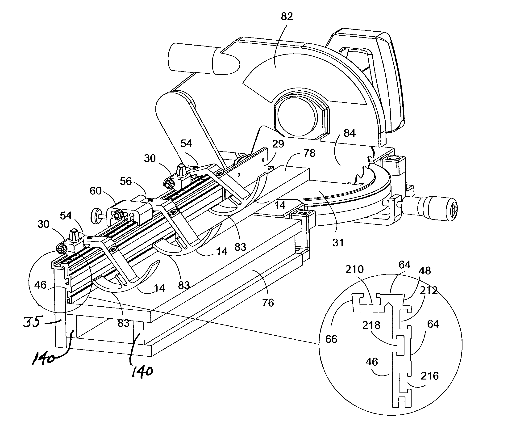
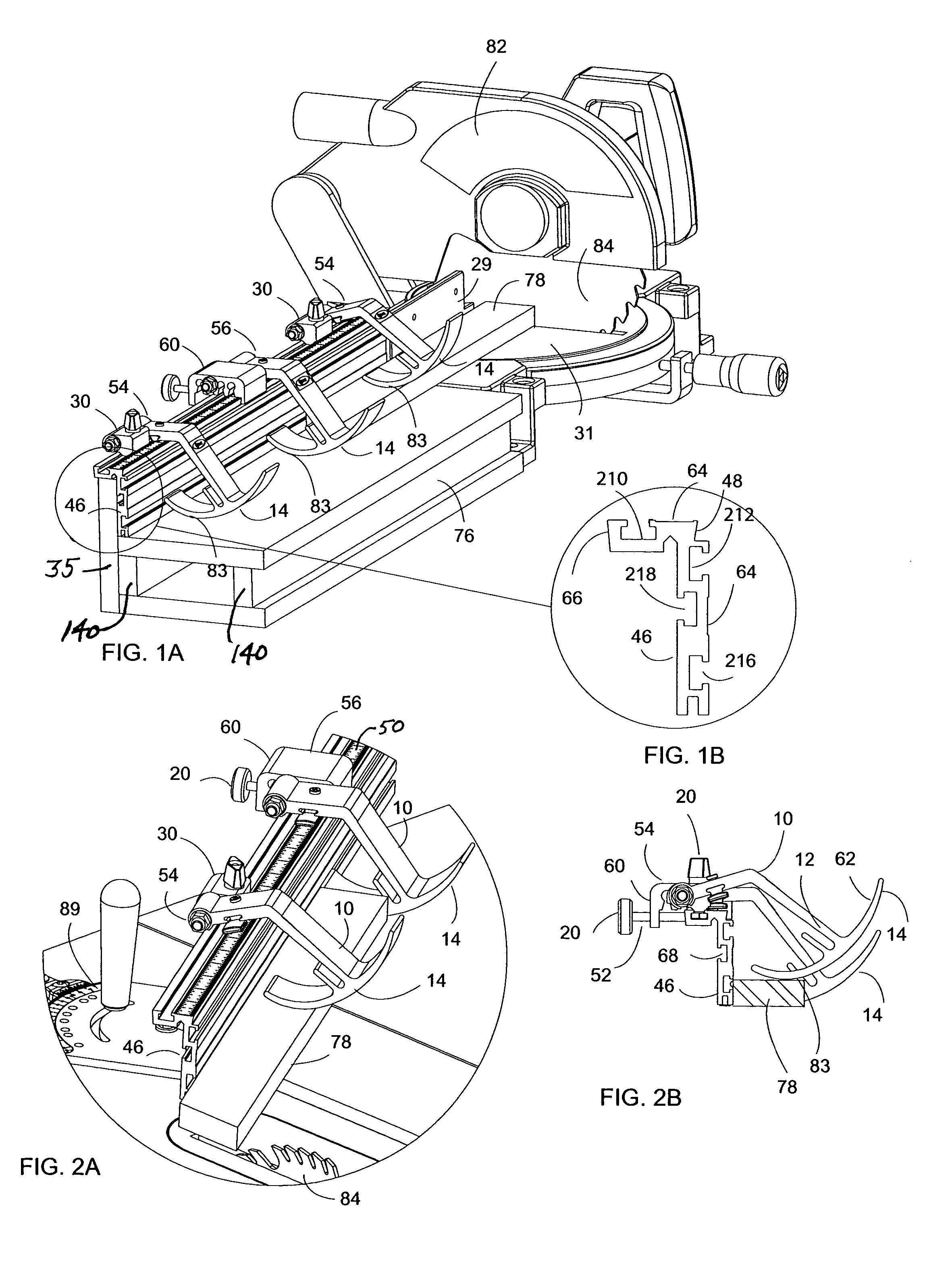
[0084]FIG. 1A illustrates a track of the invention 46, shown together with a flip stop 54 and a heavy duty flip stop 56 which are pivotable about the axis of a bolt 26 as disclosed in U.S. Pat. Nos. 5,337,641 and 5,768,966, the entire disclosures of which are hereby incorporated by reference for their teachings of how to make and use jigs and fixtures. The drawing is a perspective view of two flip stops 54 with a heavy duty flip stop 56 positioned between them. The stops are positioned on the L-shaped track 46 as it is used on a miter saw 82. The work piece 78 rests on the miter saw table auxiliary table 76 with one edge against the miter saw fence 29 and miter saw auxiliary fence 35. A wood shop-made extension table 76 is the same height as the miter saw table 31 so the work piece 80 lays flat on both tables. The extension table 76 is supported by two legs 140. A wood auxiliary fence 35 is mounted on the back of the wood shop made extension table 76. The L-shaped track 46 is an L-s...
PUM
Property
Measurement
Unit
angle
aaaaa
aaaaa
angle
aaaaa
aaaaa
thick
aaaaa
aaaaa
Abstract
A woodworking machinery jig and fixture system has a stop with a half-dovetail surface and can be provided with one or more T-slots. The half-dovetail surface can be clamped against a half-dovetail surface on the support, or against a flat surface. In one of the stops, the base has multiple through holes, any one of which can be used to mount a flip stop arm so as to vary the height of the arm or use a zero clearance fence. A track for the system has a flange that helps locate the track along the rear corner of a wood fence and also helps secure the track to the wood fence with fasteners through holes that can be drilled in the flange using a drill guide groove formed in the flange. Tension screws are provided in the stop and in the base for eliminating play between the hinge pin, the flip stop and the base. A lens is received in a groove of the stop arm and extends therefrom in position to view a ruler that is mounted on top of the support, facing up. The projection on the bottom of the base that fits into a T-slot is bordered by an angled surface that cams against the corner of the T-slot to push the other edge of the projection against the other corner of the T-slot when the base is assembled to the track, to provide a snug fit between the base and the track. The stops are provided with accessory mounting slots. A fixed stop with a half-dovetail surface, lens groove and accessory mounting slots can be mounted to a standard 2×4 that has a mating half-dovetail surface or a flat surface. A miter fixture can be mounted to the accessory slots that has fingers with ends that provide surface support of the mitered end of a workpiece whether the workpiece is supported with its point toward or away from the working plane of the support.
Description
CROSS REFERENCE TO RELATED APPLICATION[0001]This claims the benefit of U.S. Provisional Patent Application No. 60 / 503,609 filed Sep. 17, 2003.FIELD OF THE INVENTION[0002]This invention relates to shop made jigs and fixtures for positioning, aligning, guiding, and / or holding a workpiece on metalworking or woodworking machines during a cutting or shaping operation.BACKGROUND OF THE INVENTION[0003]U.S. Pat. Nos. 5,337,641, 5,617,909, and 5,768,966, the disclosures of which are hereby incorporated by reference, disclose improved jigs and fixtures for aligning, guiding, and / or holding a workpiece as it is worked, for example as it is cut, drilled, or routed. While the jigs and fixtures disclosed in U.S. Pat. Nos. 5,337,641, 5,617,909, and 5,768,966 represent a significant advance in the art, room still exists for improvements, particularly in the following respects, among others.[0004]Stops are typically secured in a T-slot of a track There is always a slight variation in the extrusion w...
Claims
Application Information
Patent Timeline
Application Date:The date an application was filed.
Publication Date:The date a patent or application was officially published.
First Publication Date:The earliest publication date of a patent with the same application number.
Issue Date:Publication date of the patent grant document.
PCT Entry Date:The Entry date of PCT National Phase.
Estimated Expiry Date:The statutory expiry date of a patent right according to the Patent Law, and it is the longest term of protection that the patent right can achieve without the termination of the patent right due to other reasons(Term extension factor has been taken into account ).
Invalid Date:Actual expiry date is based on effective date or publication date of legal transaction data of invalid patent.

