
Method and system providing sleep and wake-up modes for railway track circuit unit

a technology of railway track circuit and sleep mode, which is applied in the direction of railway signalling, transportation and packaging, and signal operation from vehicles, etc., can solve the problems of inherent delay and probably excessive time delay

Active Publication Date: 2008-12-16
ANSALDO STS USA INC
View PDF12 Cites 7 Cited by
  • Summary
  • Abstract
  • Description
  • Claims
  • Application Information

AI Technical Summary

Benefits of technology

"The present invention provides a method and system for a railway system that allows track circuit units to communicate with each other and with a train in different directions. The track circuit units enter a sleep mode and a wake-up mode based on a wireless message received from the train. The wireless message includes a first identifier of a corresponding track circuit unit and a second identifier of the direction of travel of the train. The track circuit units responsively output a signal in the first direction to the first track circuit unit or in the different second direction to the different second track circuit unit. The system includes a wireless transmitter on the train and wayside units associated with the track circuit units. The wayside units include a control circuit, a wireless receiver, and a wireless transmitter. The wireless messages are received by the wireless receiver and the control circuit responds to the wireless messages to set the control input of the track circuit units and enter the wake-up mode. The technical effect of the invention is to improve the efficiency and reliability of the railway system by allowing track circuit units to communicate with each other and with a train in different directions."

Problems solved by technology

Power to fail-over indicators, which would normally be activated due to a power failure, is also interrupted by fail-over interrupt circuitry.
Hence, in order to initiate train movement, it is required to wake-up several track circuit units with an inherent and probably excessive time delay (e.g., several minutes, depending on the number of track circuits).

Method used


Image

  • Method and system providing sleep and wake-up modes for railway track circuit unit
  • Method and system providing sleep and wake-up modes for railway track circuit unit
  • Method and system providing sleep and wake-up modes for railway track circuit unit

Examples


example 1

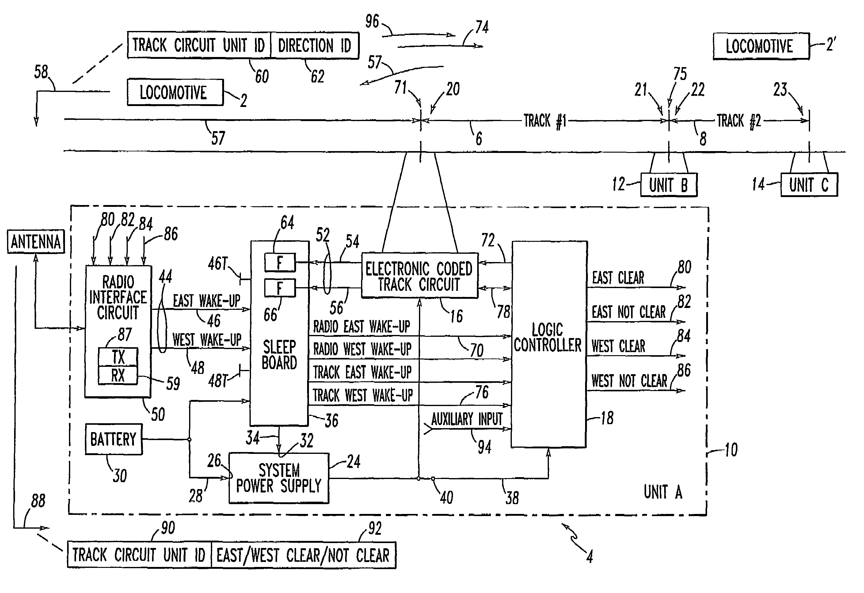
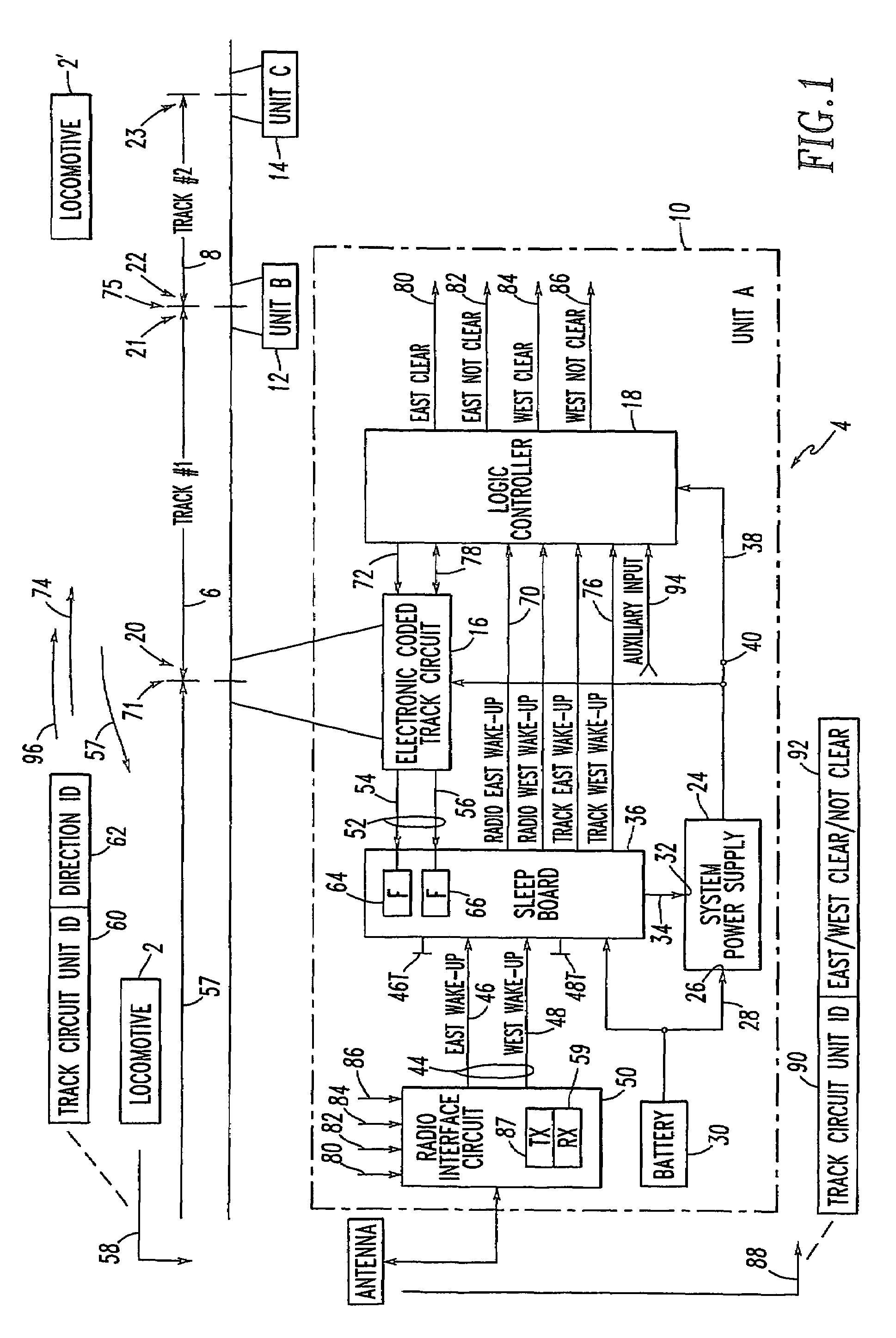
[0035]A train, such as locomotive 2, is approaching the track circuit Unit A 10 in an Easterly direction (e.g., from the left to the right side of FIG. 1). A radio message 58 with identifier 62 being East Wake-up is received by the radio interface circuit 50, which outputs the signal 46. The sleep board 36 activates the ON state of the ON / OFF signal 34 in order to activate the system power supply 24 and, also, sets a Radio East Wake-Up (REWU) signal 70 to the LC 18. The signal 70 instructs the LC 18 to begin track communication on the East side of the insulated joint 71 at location A. In response to a signal 72 from the LC 18 to the electronic coded track circuit 16, that circuit 16 sends a track message 74 on Track #16, which is received by the corresponding electronic coded track circuit 16 (not shown) of the track circuit Unit B 12. That message 74 is received on the exit or B end or East end 21 of the track circuit for Track #16, which is the West side of the insulated joint 75 ...

example 2

[0036]The signals 80,82,84,86 are output by the LC 18 to the radio interface circuit 50. The signal 84 signifies West Track Clear and the signal 86 signifies West Track Not Clear. The radio interface circuit 50 broadcasts (e.g., to the train initiating the wake-up) from radio transmitter (TX) 87 a message 88, which includes a first identifier 90 to indicate that the transmitter of the message 88 is the track circuit Unit A 10, and a second identifier 92 to indicate that the message corresponds to one of the signals 80,82,84,86.

example 3

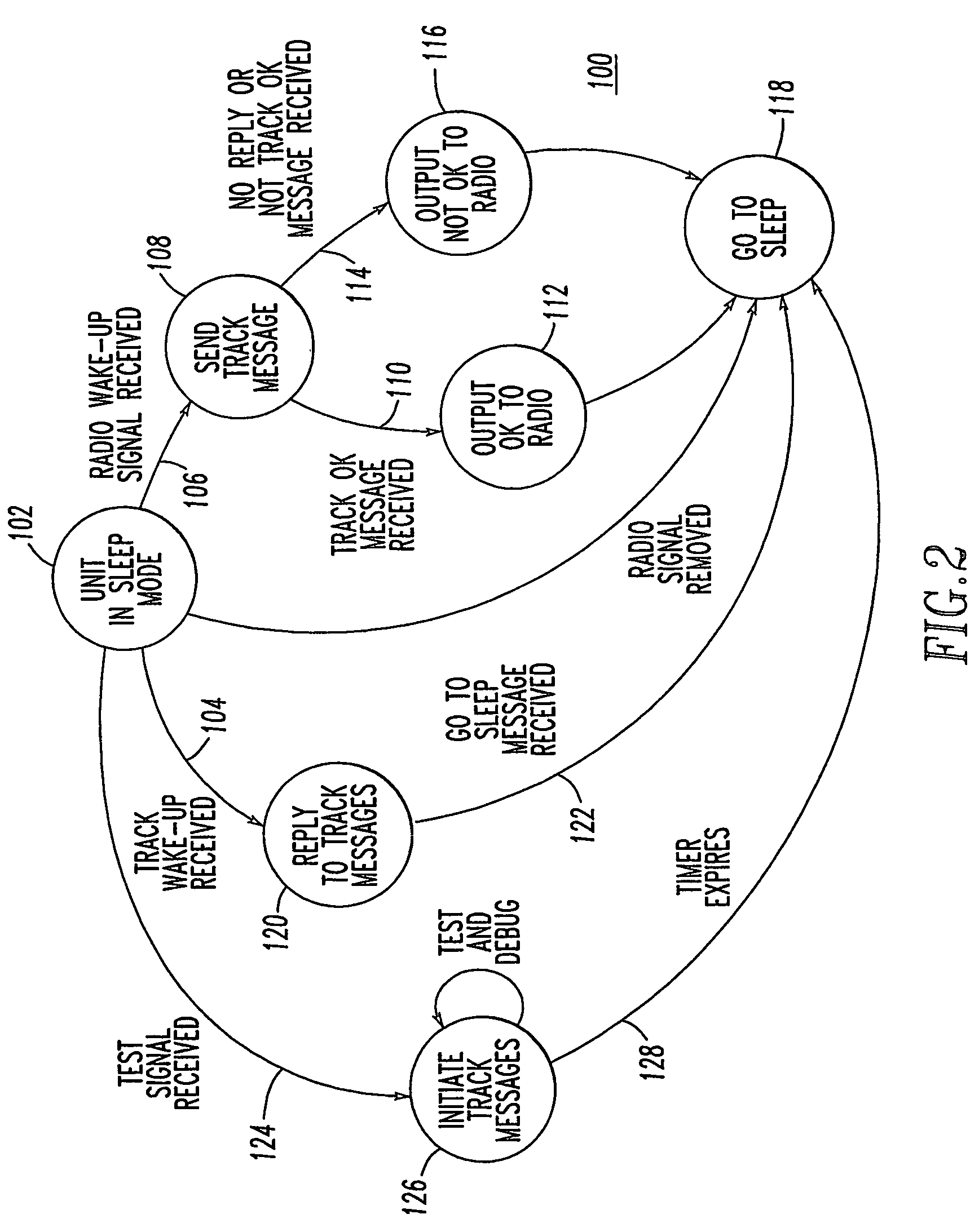
[0037]The radio message 58 from the locomotive 2 to the wayside locations, such as the track circuit Unit A 10, may be in a periodic intermittent form (e.g., 1 second on; 15 seconds off). In this manner, when the periodic intermittent messages 58 are no longer received (e.g., after a timeout of about 30 seconds), the sleep board 36 may restore the sleep mode. This occurs as a natural progression of train movement. For example, as the locomotive 2 progresses toward Track #16, there is no further need to interrogate Track #16 and the locomotive 2 would, then, radio wake up track circuit Unit B 12, in order to interrogate Track #28 and the wake-up messages 58 to track circuit Unit A 10 would terminate. Then, with the radio wake-up to track circuit Unit A 10 being terminated, that unit reverts to the power saving sleep mode. In the event that test buttons 46T,48T for the respective signals 46,48 are employed, then a longer timeout period (e.g., a number of minutes; an hour) may be emplo...


PUM


Abstract

A method provides sleep and wake-up modes for railway track circuit units. An intermediate track circuit unit communicates in a first direction to a first unit and in a different second direction to a different second unit. A plurality of wireless messages are employed between a train and a plurality of wayside units operatively associated with some of the track circuit units. Included with the wireless messages are a first identifier of a corresponding one of the track circuit units and a second identifier of a direction of travel of the train. One of the wireless messages is received at one of the wayside units corresponding to the intermediate unit based upon the first identifier. A signal is responsively output based upon the second identifier from the intermediate unit in the first direction to the first unit or in the different second direction to the different second unit.

Description

CROSS-REFERENCE TO RELATED APPLICATION[0001]This application is related to commonly assigned U.S. Provisional Patent Application Ser. No. 60 / 466,894, filed Apr. 30, 2003, entitled: “Method and System Providing Sleep Mode for Coded Railway Track Circuit Unit”.BACKGROUND OF THE INVENTION[0002]1. Field of the Invention[0003]The present invention relates to a method and system for reducing power consumption in a coded railway track circuit. More particularly, the invention relates to a method and system for placing a coded railway track circuit apparatus into a reduced power, sleep mode during periods of low vehicle activity.[0004]2. Background Information[0005]In the art of railway signaling, traffic flow through signaled territory is typically directed by various signal aspects appearing on wayside indicators or cab signal units located on board railway vehicles. The vehicle operators recognize each such aspect as indicating a particular operating condition allowed at that time. Typic...

Claims


Application Information

Patent Timeline
Patent Type & Authority Patents(United States)
IPC IPC(8): B61L21/00B61L1/18B61L3/12
CPCB61L1/188B61L3/125
Inventor VEHAR, RICHARD W.FRANKE, RAYMOND C.
Owner ANSALDO STS USA INC
Learn More