
Radio frequency envelope apparatus and method

a frequency envelope and frequency technology, applied in the field of radio frequency signals, can solve the problems of phase shift between, inherently less accurate scheme, and higher voltage level vswr (voltage standing wave ratio), and achieve the effect of increasing both the linearity and power efficiency of the amplifier

Active Publication Date: 2007-10-02
STMICROELECTRONICS SRL
View PDF3 Cites 31 Cited by
  • Summary
  • Abstract
  • Description
  • Claims
  • Application Information

AI Technical Summary

Benefits of technology

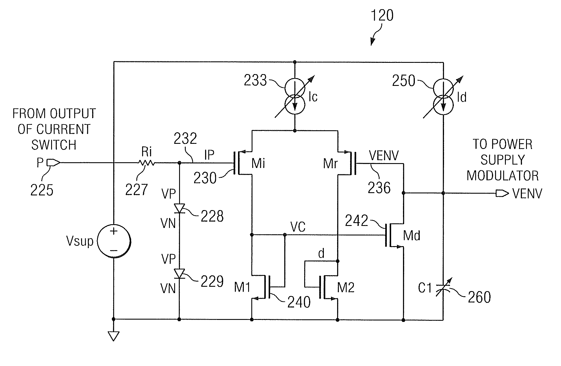
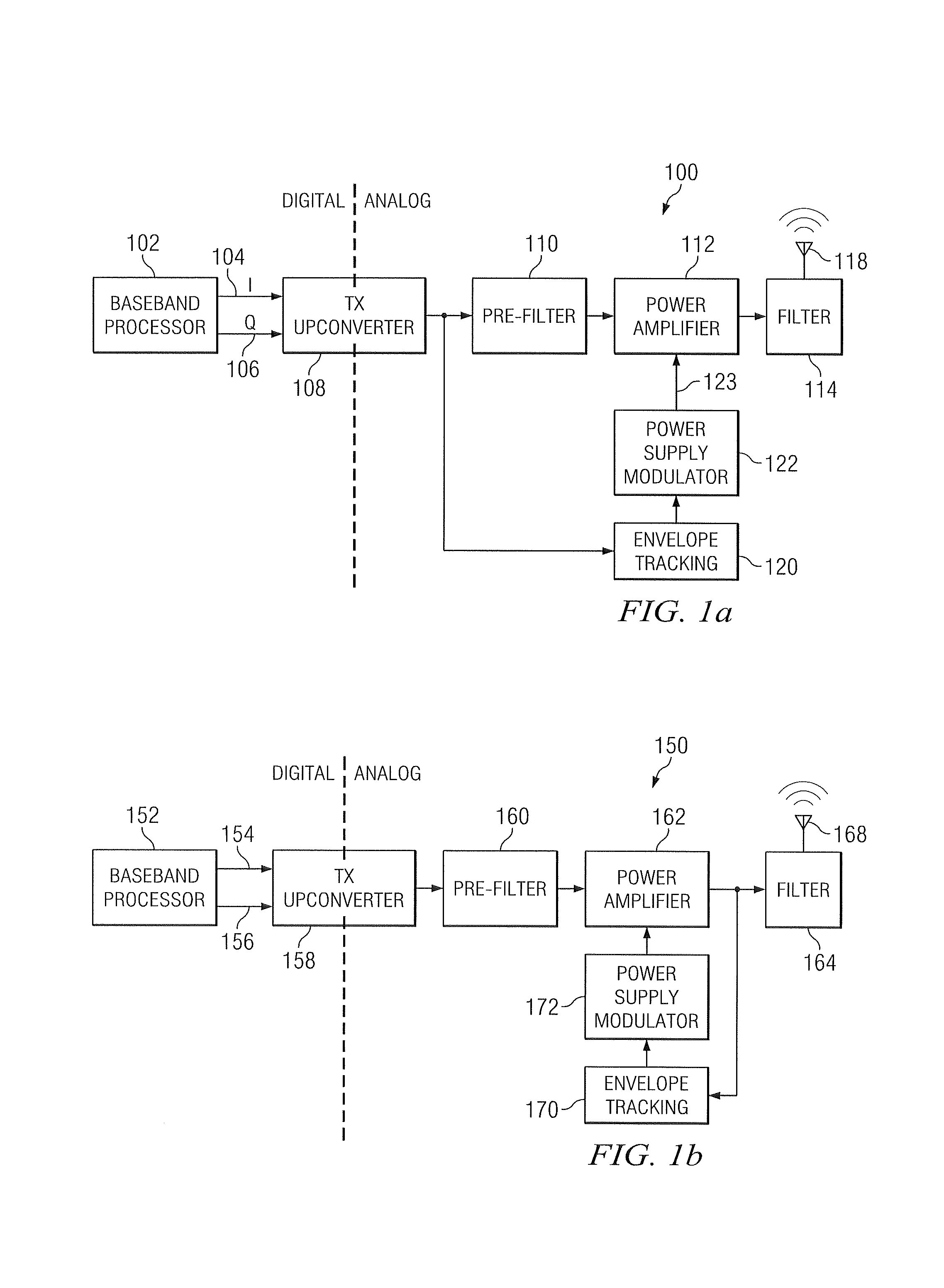
[0012]Embodiments of the present invention may be utilized in, for example, an improved RF transmitter apparatus comprising: a baseband digital processor; transmit upconverter, a power amplifier circuit, and an antenna. Such a digital baseband processor may generate digital in-phase and quadrature data streams input to the upconverter, the latter including or being coupled to an envelope tracker embodiment of the present invention adapted to modulate power applied to the amplifier according to an envelope tracking scheme. This approach increases both the linearity and power efficiency of the amplifier.

Problems solved by technology

Despite their utility, the prior art envelope tracking solutions each have one or more undesirable features or deficiencies.
For example, one salient deficiency common under the prior art relates to tracking the envelope of the input of the linear power amplifier in order to adjust the bias level.
Specifically, the disadvantage of this scheme is that the output of the power amplifier can have a reactive load, causing phase shifts between the input and output, and causing VSWR (voltage standing wave ratio) conditions with higher voltage levels than would be found with a fixed non-reactive load.
Even in the case of fixed non-reactive load, this scheme is inherently less accurate.
Thus the output voltage Y is less accurately controlled using this approach.
This RF isolator is typically quite bulky, and adds expense to the circuit as well as reduces its reliability.

Method used


Image

  • Radio frequency envelope apparatus and method
  • Radio frequency envelope apparatus and method
  • Radio frequency envelope apparatus and method

Examples


Embodiment Construction

[0025]Reference is now made to the drawings wherein like numerals refer to like parts throughout.

[0026]As used herein, the term “wireless” refers generally to any system or components which transfer energy and / or information via a wave (e.g., electromagnetic radiation such as radio waves or microwaves).

[0027]As used herein, the term “code division multiple access,” or CDMA, generally refers to digital wireless technology that uses a spread spectrum technique to disperse a signal across a wide range or band of frequencies, such as according to a pseudo-noise or other code.

[0028]As used herein, the term “upconversion” refers to any process whereby a lower frequency signal is converted to a higher frequency signal, including without limitation conversion from baseband to an intermediate frequency (IF), and conversion from baseband to carrier frequency.

Overview

[0029]Embodiments of the present invention provide, inter alia, improved apparatus and methods for envelope tracking within a wi...


PUM


Abstract

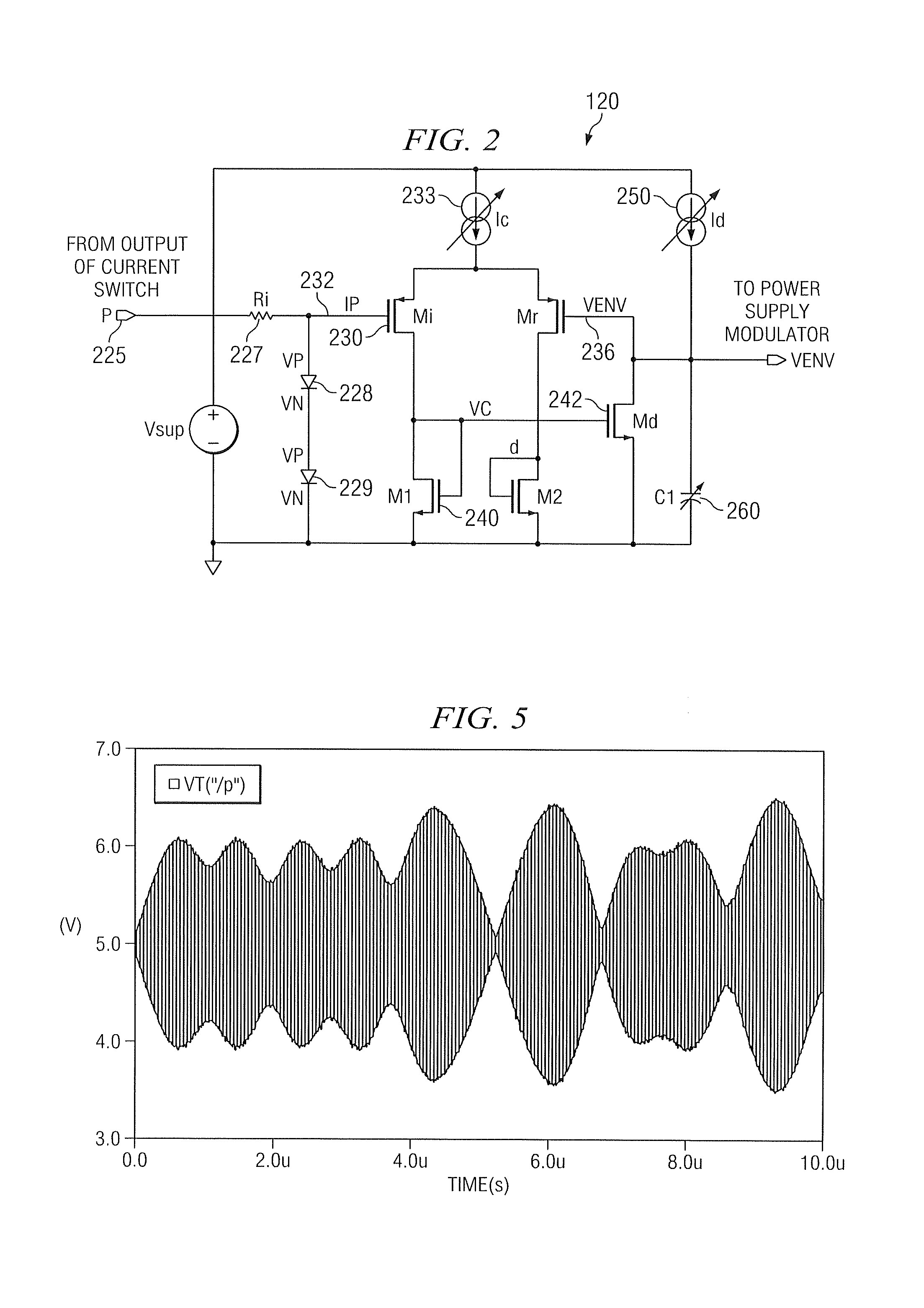
Improved radio frequency (RF) envelope tracking apparatus for use in wireless and wired systems. In one exemplary embodiment, a transmitter upconversion stage receives input digital I and Q values, the output of the upconversion stage being fed to both an envelope tracking circuit and a power amplifier (before or after optional filtering). The envelope tracking circuit controls the operation of a power modulator, which adjusts the power amplifier. The envelope tracking circuit is specifically configured to provide improved linearity and power efficiency. The envelope tracking apparatus and methods of the present invention may be applied to heterodyne / super-heterodyne architectures as well as others.

Description

PRIORITY AND RELATED APPLICATIONS[0001]This application claims priority to U.S. Provisional Application Ser. No. 60 / 515,377 filed Oct. 28, 2003 and entitled “IMPROVED RADIO FREQUENCY ENVELOPE APPARATUS AND METHOD”.FIELD OF THE INVENTION[0002]The present invention relates generally radio frequency signals, and specifically for efficient apparatus and methods for radio frequency (RF) signal transmission, reception, and modulation.DESCRIPTION OF RELATED TECHNOLOGY[0003]Wireless radio frequency (RF) power amplifiers are now ubiquitous, and used in any number of different devices including wireless and cellular telephones, WLAN devices, and the like. As is known, dynamically tracking the envelope of the input of such power amplifiers, and using that tracking information to control the bias level of the amplifier, has several potential benefits including, inter alia: 1) improved power added efficiency (PAE), and 2) improved linearity.[0004]Despite their utility, the prior art envelope tra...

Claims


Application Information

Patent Timeline
IPC IPC(8): H03G3/20
CPCH03F1/0222H03F1/0233H03F1/32H03F1/3211H03G3/3042H03F3/45183H03F1/3294H03F2200/102H03F2203/45568
Inventor THAM, ANDREWNORSWORTHY, STEVEN R.REDGRAVE, JASON RUPERT
Owner STMICROELECTRONICS SRL
Learn More