Life raft

a life raft and raft body technology, applied in the field of life rafts, can solve the problems of failure of the towing line attachment, loose engagement of the lashing, and risk of failure or tearing under heavy loads, and achieve the effects of excellent flexibility, low cost and high mechanical strength

Inactive Publication Date: 2008-12-16
Z MARINE INT
View PDF7 Cites 0 Cited by
  • Summary
  • Abstract
  • Description
  • Claims
  • Application Information

AI Technical Summary

Benefits of technology

[0008]It is therefore an object of the invention to provide an improved life raft structure that satisfies practical demands better than is currently the case.
[0010]With this improved structure, towing forces are no longer applied to individual points of the float but are taken by the belt only. This belt is in the general shape of a loop which encircles the float in such a way that, during towing, it is the belt which is pulled and the towing forces are not communicated at any time to the float. By selecting a belt which has the appropriate mechanical strength, the raft becomes able to withstand very high towing forces without damage.
[0012]However, in a preferred embodiment, the belt is made of woven or braided material and is stitched to a strip of substrate which in turn is made of a material suitable for adhesively bonding or welding to the outer face of the float. Thus produced in woven or braided form, the belt is less prone to tearing and its mechanical tensile strength is increased.
[0013]It is preferable for the belt to be formed by two half-belts encircling two respective half-peripheries of the float. This configuration will make it easier to fix the belt to the float because it avoids the necessity of grappling with one piece of too great a length when attaching it.
[0016]The arrangements of the invention can have a particularly useful application where the float is made up of at least two superposed inflatable tubes and the two tubes are held at a distance from each other and connected together by a strip of intermediate material, in which case the belt is advantageously fixed to the outer face of said intermediate strip between the two tubes. The advantage of this option is that the belt is not attached directly to a pneumatic part and can therefore be treated as a simple mechanical member of the raft, particularly as regards the fixing of the accessories which can admittedly be stitched on as explained earlier, but can also be attached by other mechanical means such as staples, threaded fasteners, rivets, etc.
[0020]An additional advantage of the provisions of the invention should be stressed here, namely that it is possible to make the float of the raft from a composite material consisting of a layer of watertight synthetic material sandwiched between two textile layers, the advantage of such a material being its excellent flexibility and hence the ease with which it can be folded and stored in a container; besides which, such a material is less expensive than the materials usually employed. However, the outer textile layer is unsuitable for welding an accessory or an accessory support, such as a ring for attaching a towing line; and although adhesive bonding is still possible, the mechanical strength of adhesive bonding is insufficient to withstand a large tensile force such as can occur during towing. The provisions of the invention therefore allow the use of the above composite material to be reconciled with high mechanical strength of the float under tensile forces.

Problems solved by technology

However, the problem with such an arrangement is that the entirety of the tractive force is applied to the wall of the float in a very localized manner at one or two points and its reliability depends entirely on the mechanical strength of the fixings and of the wall.
In practice, there have been incidents in which the attachment of the towing line has failed due to detachment of the ring retention loop or local tearing of the float wall.
The problem with this approach is that the lashing is engaged loosely through loops and is not rigidly fixed to the float itself.
The tensile force applied to the lashing is thus transferred to the float in an irregular way at local points of the float (loops, fixings of the ends of the lashing), and there is still a risk of failure or tearing under heavy loads.
Furthermore, if the lashing fails the towing option is lost.
Currently known life raft arrangements fail to meet these new requirements in any certain and reliable way.

Method used


Image

  • Life raft
  • Life raft
  • Life raft

Examples


Embodiment Construction

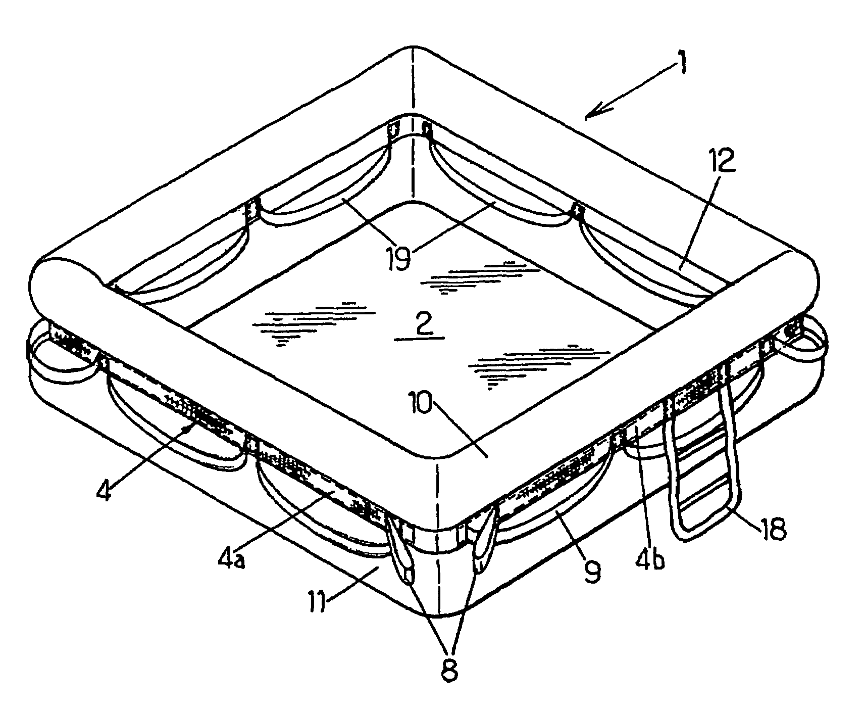
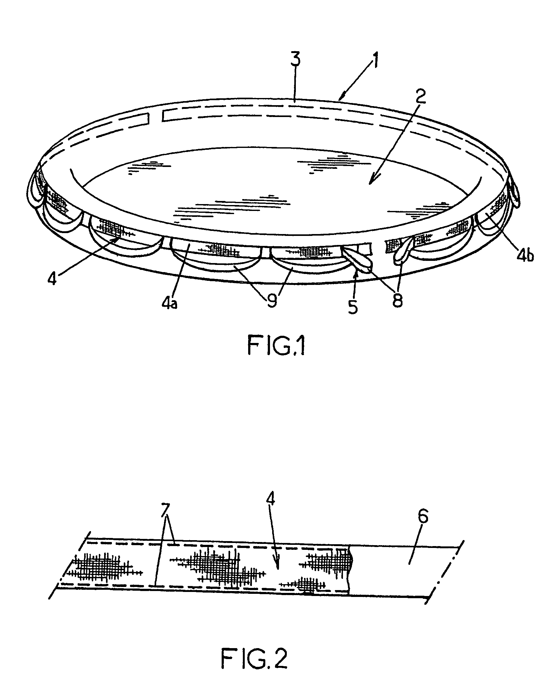
[0026]Referring initially to FIG. 1, this shows an inflatable life raft comprising a pneumatic float 1 running around the periphery and a flexible bottom 2 fixed underneath the float 1. In this example, the float 1 is a single inflatable tube 3 and is generally circular.

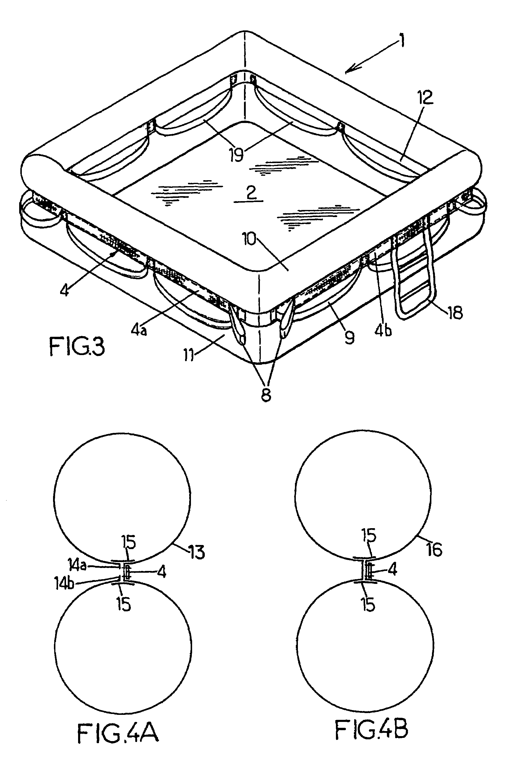
[0027]The invention provides that a belt 4 having good mechanical strength extends all the way around the periphery of the float 1 and is fixed to it all the way along its length, and that this belt 4 supports or incorporates fixing means 5 for at least one towing line.

[0028]In this arrangement, towing forces are taken by the belt alone: this belt is in the general form of a loop running around the float in such a way that, during towing, it is the belt that is towed and that pulls the float which it encircles, no part of the float being at any time subjected to traction. By selecting a belt that possesses the appropriate mechanical strength, the raft is thus able to withstand very high towing forces without damage.

[...


PUM


Abstract

The inventive inflatable life raft comprises a peripheral pneumatic float (1) and a bottom (2) fixed thereto and is characterised in that a mechanically résistant belt (4) extends along the float (1) circumference, is fixed thereto along the entire length thereof and said belt (4) bears or incorporâtes fixing means (8) for at least one towing line in such a way that towing forces are distributed through the entire circumference of the float and the raft can withstand high towing forces without any damages.

Description

CROSS REFERENCE TO RELATED APPLICATIONS[0001]This application is the U.S. national phase of International Application No. PCT / FR2005 / 001555 filed on Jun. 21, 2005 and published as International Publication No. WO 2006 / 010808 A1, which application claims priority to French Patent Application No. 04 07026 filed on Jun. 25, 2004, the contents of which are incorporated by reference herein.FIELD OF THE INVENTION[0002]The present invention relates to improvements to life rafts of inflatable type comprising a peripheral pneumatic float and a bottom fixed to said float.BACKGROUND OF THE INVENTION[0003]Life rafts must be able to be towed by means of towing lines. To this end, life rafts are equipped with a member, such as a ring or the like, appropriate for attaching the end of the towing line. This ring is usually fixed to the wall of the float via a loop made of a flexible material which in turn is fixed (e.g. by adhesive bonding or welding) to the float wall.[0004]An arrangement of the ab...

Claims


Application Information

Patent Timeline
Patent Type & Authority Patents(United States)
IPC IPC(8): B63B35/58B63B7/00B63B7/08B63C9/04
CPCB63C9/04B63B7/08
Inventor SCHLOEGEL, CHRISTIAN
Owner Z MARINE INT
Why Eureka
Try Eureka