
Internal combustion engine with an air separator and methods for realizing such an internal combustion engine

an internal combustion engine and separator technology, applied in the direction of machines/engines, combustion-air/fuel-air treatment, separation processes, etc., can solve the problems of loss of separation capacity, reduced nitric oxide formation in the combustion space of the internal combustion engine, and heavy dependence on the separation capacity of conventional air separation units, etc., to achieve optimal separation of intake air, reduce nitric oxide formation, and increase oxygen content

Inactive Publication Date: 2008-12-16
DAIMLER AG
View PDF13 Cites 17 Cited by
  • Summary
  • Abstract
  • Description
  • Claims
  • Application Information

AI Technical Summary

Benefits of technology

The present invention is about an internal combustion engine with an air separator for the separation of intake air. The air separator uses a membrane separation unit to separate the air into two compositions: one enriched with oxygen-rich permeate and one enriched with nitrogen-rich retentate. The engine can alternately be fed with nitrogen- or oxygen-enriched intake air, which reduces pollutant emissions. The air separation unit is connected to the outlet of the charging unit and is designed to improve reliability, increase air separation capacity, and reduce installation space. The purification unit can remove contaminants from the air supply to keep the air separation unit clean. The addition of oxygen-enriched intake air can improve combustion and reduce soot formation. The technical effects of the invention include improved engine performance, reduced emissions, and increased reliability and durability of the air separation unit.

Problems solved by technology

Enriching the intake air with nitrogen lowers the combustion temperatures, which leads to a decrease in nitric oxide formation within the combustion space of the internal combustion engine.
The separation capacity of conventional air separation units, however, is heavily dependent on service conditions like working pressure and air flow rate.
A rise in air flow rate results in a loss of separation capacity, i.e., the degree of permeate and retentate enrichment as related to the design volume of the air separation unit.

Method used


Image

  • Internal combustion engine with an air separator and methods for realizing such an internal combustion engine
  • Internal combustion engine with an air separator and methods for realizing such an internal combustion engine
  • Internal combustion engine with an air separator and methods for realizing such an internal combustion engine

Examples


Embodiment Construction

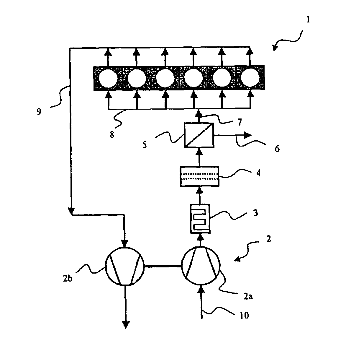
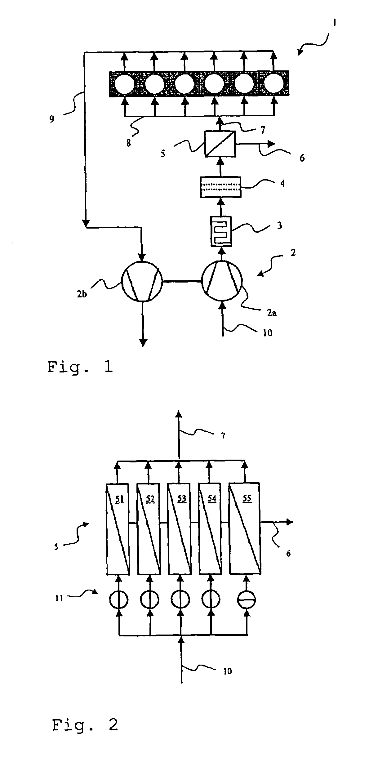
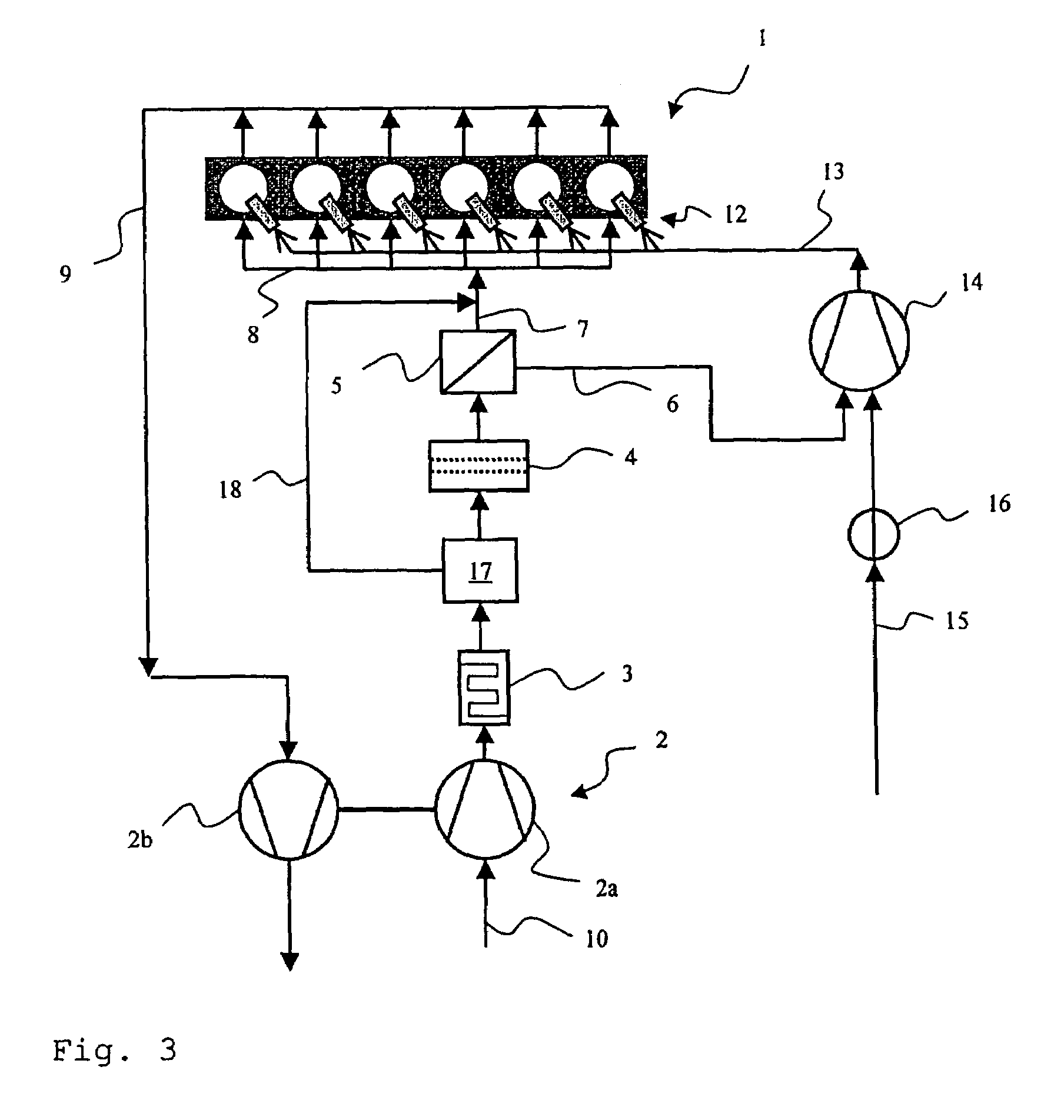
[0026]FIG. 1 is a schematic block diagram of a first advantageous embodiment of the internal combustion engine according to the invention. This comprises a six-cylinder straight block type air compressing combustion engine 1. The engine 1 is equipped with an exhaust gas turbo-charger 2 with a turbine 2b inside an exhaust gas line 9 and a compressor 2a in an air intake line 10. A charged air cooler 3 is connected to the outlet of the compressor 2a for cooling compressed intake air. Further, in the air flow of the already compressed and cooled intake air is arranged a purification unit 4, which enables the purification of compressed intake air. Connected to the outlet of the purification unit 4 is an air separation unit 5, which makes available an oxygen-enriched permeate through a permeate outlet 6 and a nitrogen-enriched retentate through a retentate outlet 7. The retentate outlet 7 of the air separation unit 5 is joined to the intake manifold 8 of the engine 1. The retentate provid...


PUM

PropertyMeasurementUnit
pressureaaaaaaaaaa
pressureaaaaaaaaaa
permeate flowaaaaaaaaaa

Abstract

In an internal combustion engine with an air separation unit and a method of realizing such an internal combustion engine, the air separation unit is able to be fed by intake air compressed by a charging unit and cooled by a charged air cooler. The internal combustion engine can at least periodically be fed with a retentate, provided by the air separation unit, having such a composition that, in comparison to normal, it is oxygen enriched. The air separation unit is connected to the outlet of the charged air cooler, and compressed intake air from the charging unit undergoes purification that includes the separation of fluid and / or solid contents before being fed into the air separation unit.

Description

[0001]This application claims the priority of German application 10 2004 041 263.4, filed Aug. 26, 2004, the disclosure of which is expressly incorporated by reference herein.BACKGROUND AND SUMMARY OF THE INVENTION[0002]The present invention concerns an internal combustion engine with an air separator for the separation of intake air of a composition that, in comparison to normal, is enriched with an oxygen-rich permeate and a nitrogen-rich retentate, and a method for realizing such an internal combustion engine.[0003]An internal combustion engine which can be fed with nitrogen- or oxygen-enriched intake air is known from U.S. Pat. No. 6,173,567 B1. The process of enriching the intake air takes place via the respective air accessories and a membrane separator, which is capable of providing two air supplies, one enriched with the oxygen-rich permeate, the other with the nitrogen-rich retentate. The use of an internal combustion engine alternatively enriched with oxygen-rich and nitro...

Claims


Application Information

Patent Timeline
Patent Type & Authority Patents(United States)
IPC IPC(8): B01D53/22F02B23/00
CPCF02M25/12F02M33/00F02M27/02Y02T10/121Y02T10/12
Inventor GAERTNER, UWEKOCH, THOMAS
Owner DAIMLER AG
Learn More