Dual-band antenna

a dual-band antenna and antenna technology, applied in the direction of elongated active element feed, resonant antenna, radiating element structure, etc., can solve the problems of reducing the efficiency of the dual-band antenna in the lower frequency band and the efficiency of the multi-band antenna, so as to reduce the interference between the short portion and the first radiating portion. , the effect of reducing the interference between the short portion and the first radiating portion

Inactive Publication Date: 2008-12-16
CHENG UEI PRECISION IND CO LTD
View PDF7 Cites 16 Cited by
  • Summary
  • Abstract
  • Description
  • Claims
  • Application Information

AI Technical Summary

Benefits of technology

[0013]When the antenna operates at wireless operation, the resonance of the connection portion and the first radiating portion obtain a lower frequency range, and the resonance of the connection portion and the second radiating portion obtain a higher frequency range. The resonance of the short portion is as a function of an inductance. Because the acute angle is formed between the short portion and the ground portion, and the first radiating portion, the short portion is obliquely arranged between the ground portion and the first radiating portion. Therefore, the average interference between the short portion and the first radiating portion is reduced.

Problems solved by technology

The electromagnetic interference between the second radiating strip and the third segment may influence antenna characteristic of the lower frequency band of the dual-band antenna to decrease the efficiency of the lower frequency band of the dual-band antenna.
The electromagnetic interference between the radiating element and the third segment may influence antenna characteristic of the multifrequency antenna to decrease the efficiency of the multifrequency antenna.

Method used


Image

  • Dual-band antenna
  • Dual-band antenna
  • Dual-band antenna

Examples


Embodiment Construction

[0019]Structures of a dual-band antenna described herein are sized and shaped to tune the dual-band antenna for operation in wireless telecommunication bands. In an embodiment of the invention described in detail below, the dual-band antenna has structure which is primarily associated with operating bands covering 2.4 GHz band and 5.2 GHz band.

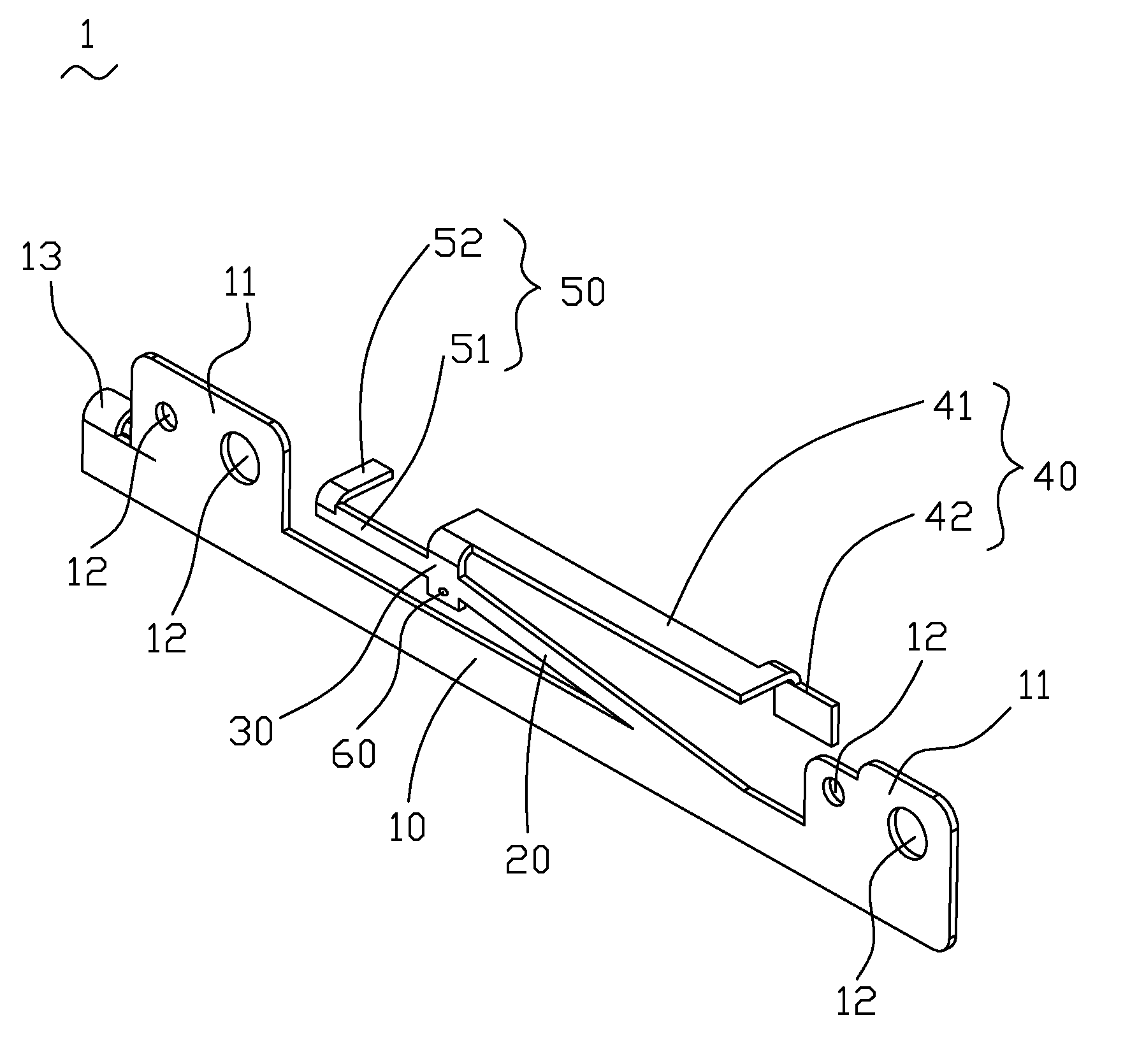
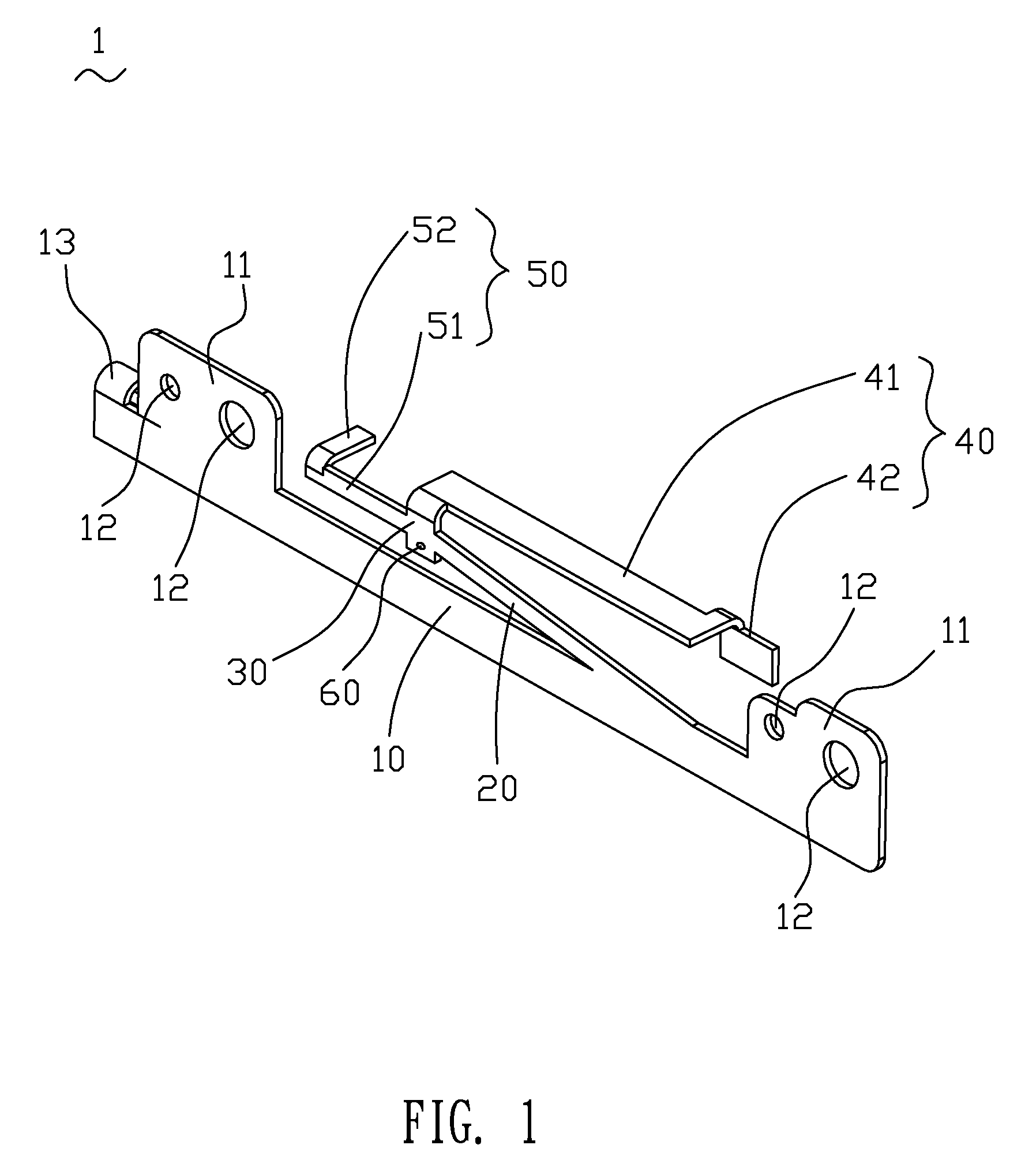
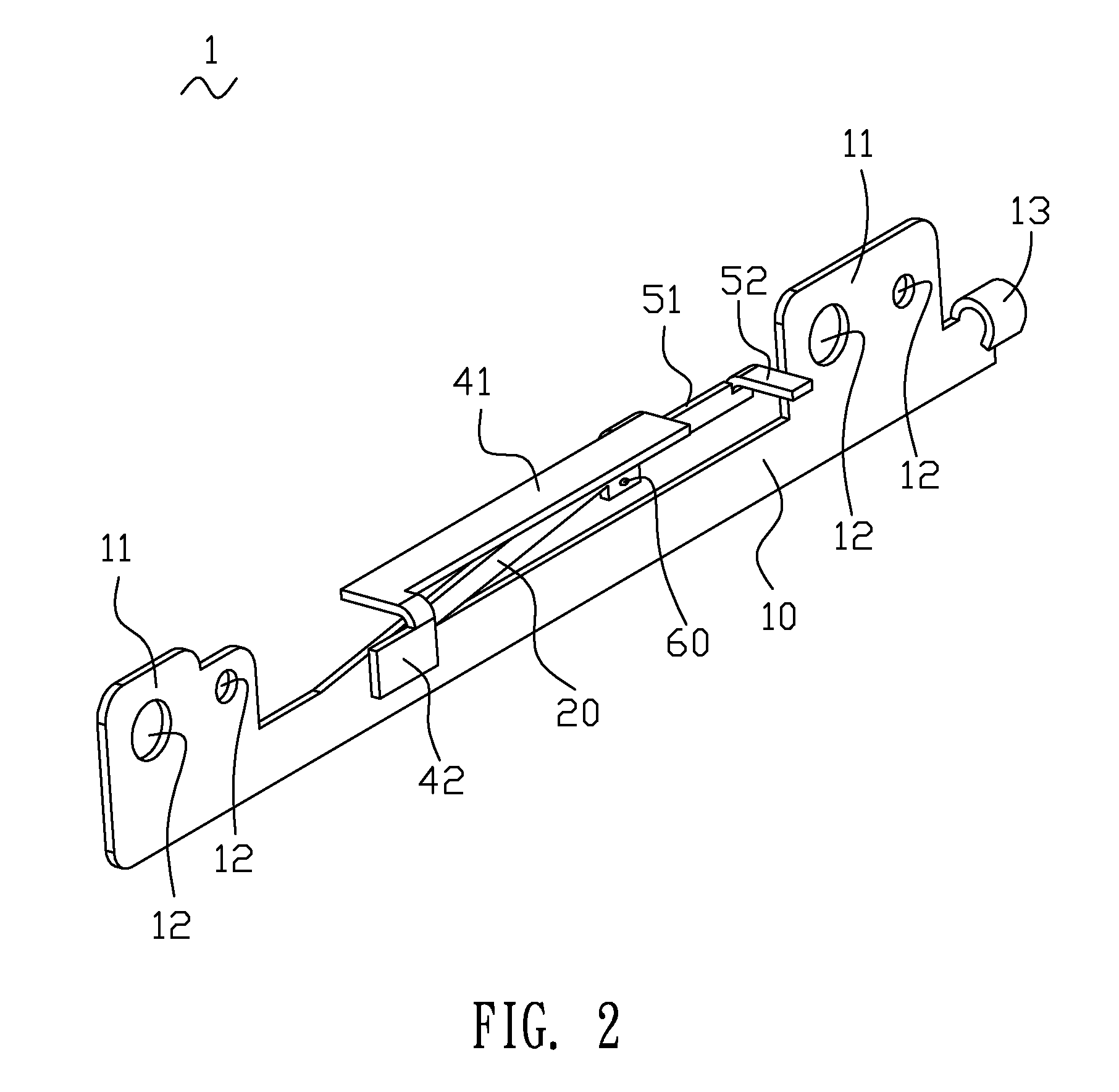
[0020]Please refer to FIG. 1 and FIG. 2. A preferred embodiment of the dual-band antenna 1 according to the present invention is shown. The dual-band antenna 1 has a ground portion 10, a short portion 20, a connection portion 30, a first radiating portion 40 and a second radiating portion 50.

[0021]In this case, the ground portion 10 is an elongated plate and defines opposite ends. Two fixing plates 11 are arranged at opposite ends of the ground portion 10 and extend from one side of the ground portion 10. The fixing plates 11 and the ground portion 10 are arranged at same plane. Pluralities of through holes 12 are opened on the fixing plates 1...


PUM


Abstract

A dual-band antenna has a ground portion, a connection portion with a feeding point separated from the ground portion and a short portion connected to the ground portion and the connection portion. The short portion and the ground portion are formed an acute angle therebetween. The connection portion respectively connect a first radiating portion and a second radiating portion. The first radiating portion and the second radiating portion are parallel to said ground portion. The short portion is arranged between the ground portion and the first radiating portion. When the dual-band antenna operates at wireless operation, the connection portion, the first radiating portion and the second radiating portion resonate to obtain a first frequency range and a second frequency range. The short portion is formed as a function of an inductance.

Description

BACKGROUND OF THE INVENTION[0001]1. Field of the Invention[0002]The invention relates to the field of antenna. More specifically, a dual-band antenna has a short portion as a function of an inductance.[0003]2. The Related Art[0004]According to the progress of the communication technology, the key development is the transfer from wired to wireless communication. A plurality of different wireless communication bands may be used by devices such as laptops. Therefore, antennas equipping multi-frequency operation for the laptops are one of the development points.[0005]A conventional dual-band antenna is disclosed in U.S. Pat. No. 6,812,892 filed in 2002 Dec. 26. The dual band antenna has a planar conductive element and a feeder cable electronically connecting to the conductive element. The conductive element includes a first radiating strip, a second radiating strip, a ground portion and a connection strip interconnecting the first and the second radiating strips with the ground portion....

Claims


Application Information

Patent Timeline
Patent Type & Authority Patents(United States)
IPC IPC(8): H01Q1/38
CPCH01Q1/2266H01Q5/371H01Q9/42
Inventor SU, JIA-HUNGLIN, CHING-CHIHU, SHIH-HAOCHEN, HUNG-JENSHIH, KAIWU, YU-YUAN
Owner CHENG UEI PRECISION IND CO LTD
Why Eureka
Try Eureka