Protection device for bus systems

a protection device and bus system technology, applied in logic circuit coupling/interface arrangement, pulse technique, instruments, etc., can solve the problem of restricted and achieve the effect of reducing the currently required effort, reducing the capacitance of the capacitor, and reducing the frequency range of irradiation interference to be attenuated

Active Publication Date: 2008-11-25
ROBERT BOSCH GMBH
View PDF5 Cites 1 Cited by
  • Summary
  • Abstract
  • Description
  • Claims
  • Application Information

AI Technical Summary

Benefits of technology

[0008]An important advantage of the present invention is that it considerably reduces the currently required effort; only one diode will be required while simultaneously retaining the protective effect and expanding, toward deeper frequencies, the frequency range of irradiation interference to be attenuated. Furthermore, the capacitance of a capacitor is considerably reduced in each connected device, resulting not only in economic advantages but in dimensional advantages as well.
[0009]Furthermore, this advantageously allows the basic capacitance of the central capacitor to be essentially constant, regardless of the number of connected devices, i.e., compared to the related art the effective frequency range to be attenuated is less dependent on the number of connected devices.
[0010]An electrical protection device for bus systems according to the present invention, in particular one having a two-wire design, which includes a bus control unit and at least one device connected to a bus, is characterized by the protection device being arranged in a central location on the bus and being connected thereto.
[0011]In a preferred refinement, the at least one connected device has a device-protection unit so that the frequency range to be attenuated is expanded in an advantageous manner.
[0012]In another preferred embodiment, the protection device has at least one protective diode and a protective capacitor, and the device-protection unit has a second capacitor, the capacitance of the second capacitor essentially being lower than the capacitance of the protective capacitor of the protection device. In this way, a high basic capacitance is arranged in a central location in the bus system, and a multitude of individual diodes and capacitors for each individual connected device is dispensed with, which results in an economic advantage.
[0013]Another embodiment provides that the protection device be arranged in a bus distributor. This utilizes the installation space available in the bus-distributor unit in an advantageous manner. No additional housing will be required.

Problems solved by technology

This produces a d.c. voltage on the bus line, which superimposes itself on the transmission voltages on the bus line and thus may cause interference.
However, their capacitance must not exceed a certain relatively low value since this capacitance puts a capacitive load on the bus with each connected device.
The frequency range of the irradiation interference to be attenuated is restricted as a result.

Method used


Image

  • Protection device for bus systems
  • Protection device for bus systems

Examples


Embodiment Construction

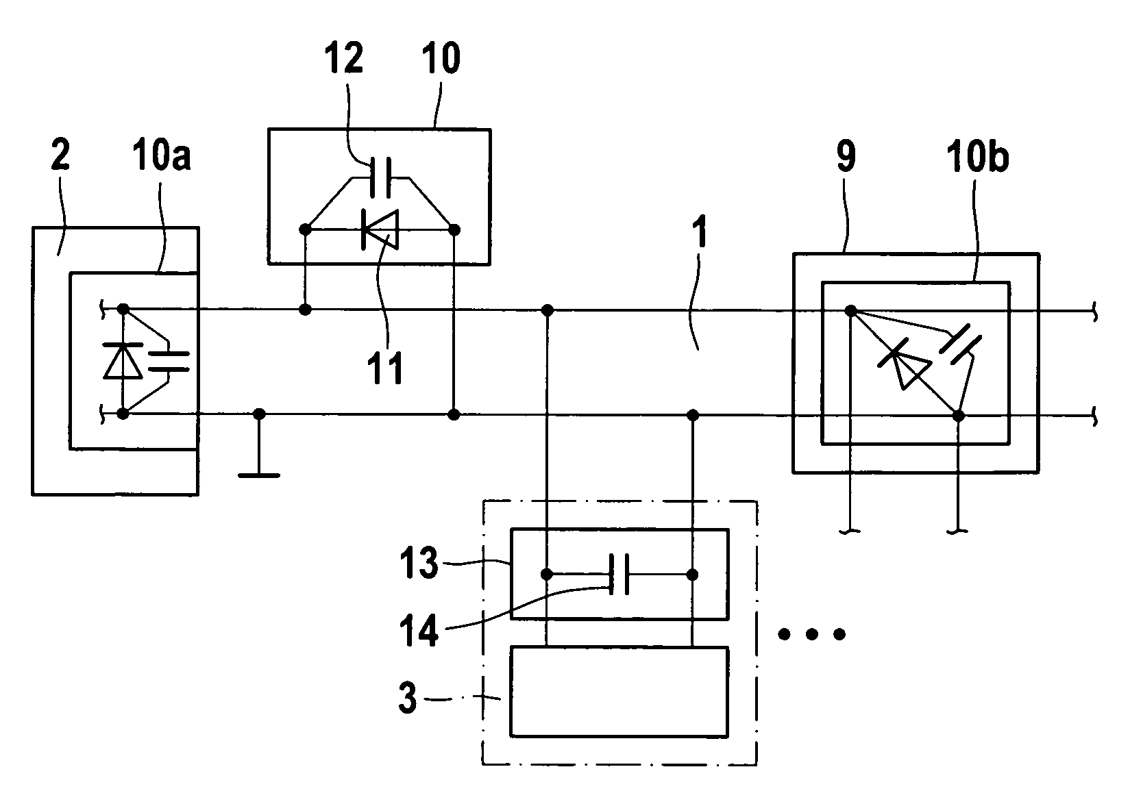
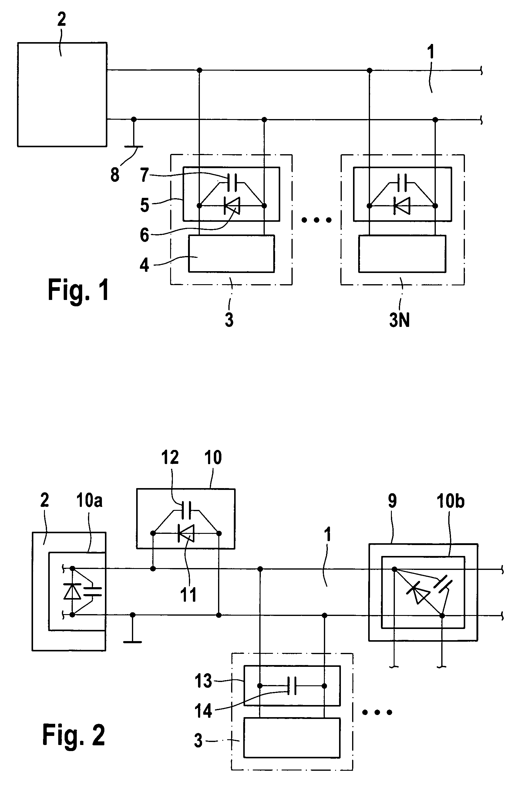
[0019]FIG. 1 shows a block diagram of a bus system configured according to the related art. The bus system has a bus control unit 2. Bus control unit 2 is connected to bus 1 which, in the example illustrated, is made up of a two-wire line. One of the two lines of bus 1 is connected to ground 8. Bus-control unit 2 carries out the control of the bus system in the conventional manner; it supplies voltage to devices 3, 3N connected to bus 1, transmits data thereto and receives data transmitted from devices 3, 3N, processes and / or forwards these data to higher-order evaluation units (not shown).

[0020]Furthermore, devices 3 to 3N are connected to bus 1 by two lines in each case. Device 3, 3N may have different functions such as a sensor function, and includes a device circuit 4 which is connected to the bus lines. These connecting lines run through a first device-protection unit 5. Inside device protection unit 5 the connection lines are connected to a diode 6 to which a capacitor is swit...


PUM


Abstract

An electrical protection device for bus systems, in particular having a two-wire design, including a bus-control unit and at least one device connected to a bus, the protection device being arranged in a central location on the bus and connected thereto.

Description

FIELD OF THE INVENTION[0001]The present invention relates to an electrical protection device for bus systems, in particular for bus systems having a two-wire design.BACKGROUND INFORMATION[0002]Such bus systems are made up of a control device having a multicore line—in this case a two-wire design, in particular—to which devices such as, for example, up to 30 items having different functions but sharing a uniform interface are connected. In a two-wire bus system, the line, which is made up of only two wires, is used for different purposes simultaneously. For one, electrical energy for the supply of the connected devices is transmitted via the bus line and, for another, the bus line transmits data to the connected devices and from there to the control device.[0003]Such a bus system is used in different application areas, for instance in the manufacturing industry, in households, motor vehicles, and many other places, and is exposed to a multitude of electrical and electromagnetic influ...

Claims


Application Information

Patent Timeline
Patent Type & Authority Patents(United States)
IPC IPC(8): H02H3/22H02H3/00
CPCG06F13/4072
Inventor WIZEMANN, THOMASWENZLER, PATRICKCASARES, MIGUEL
Owner ROBERT BOSCH GMBH
Why Eureka
Try Eureka