Method for governing the operation of a pneumatic impulse wrench and a power screw joint tightening tool system

Inactive Publication Date: 2008-12-23
ATLAS COPCO TOOLS AB
View PDF26 Cites 13 Cited by
  • Summary
  • Abstract
  • Description
  • Claims
  • Application Information

AI Technical Summary

Benefits of technology

[0007]It is an object of the invention to provide a method for governing a screw joint tightening process performed by a pneumatic impulse wrench which does not require any pre-tightening calibration procedures and which is controlled in such a way that overtightenin

Problems solved by technology

A problem concerned with pneumatically powered impulse wrenches is the difficulty to govern the tightening process accurately enough to ensure a correct and reliable pre-tensioning result.
This known tightening system has two weak points from the reliability point of view, namely that the actual instantaneous tightening parameter values, like the torque magnitude, are obtained from an easily disturbed torque transducer including a magnetostrictive output shaft portion and electric coils mounted in the impulse wrench housing.
This arrangement is not only sensitive to external disturbances resulting in a less reliable torque magnitude detection but it is rather space demanding and adds in a negative way to the outer dimensions of the impulse wrench.
Although this prior art p

Method used


Image

  • Method for governing the operation of a pneumatic impulse wrench and a power screw joint tightening tool system
  • Method for governing the operation of a pneumatic impulse wrench and a power screw joint tightening tool system
  • Method for governing the operation of a pneumatic impulse wrench and a power screw joint tightening tool system

Examples


Embodiment Construction

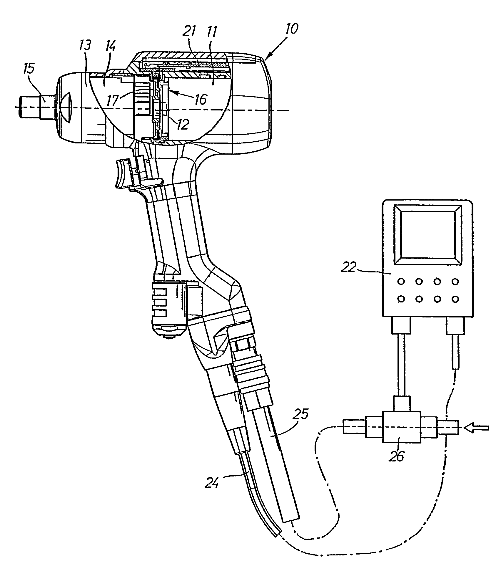
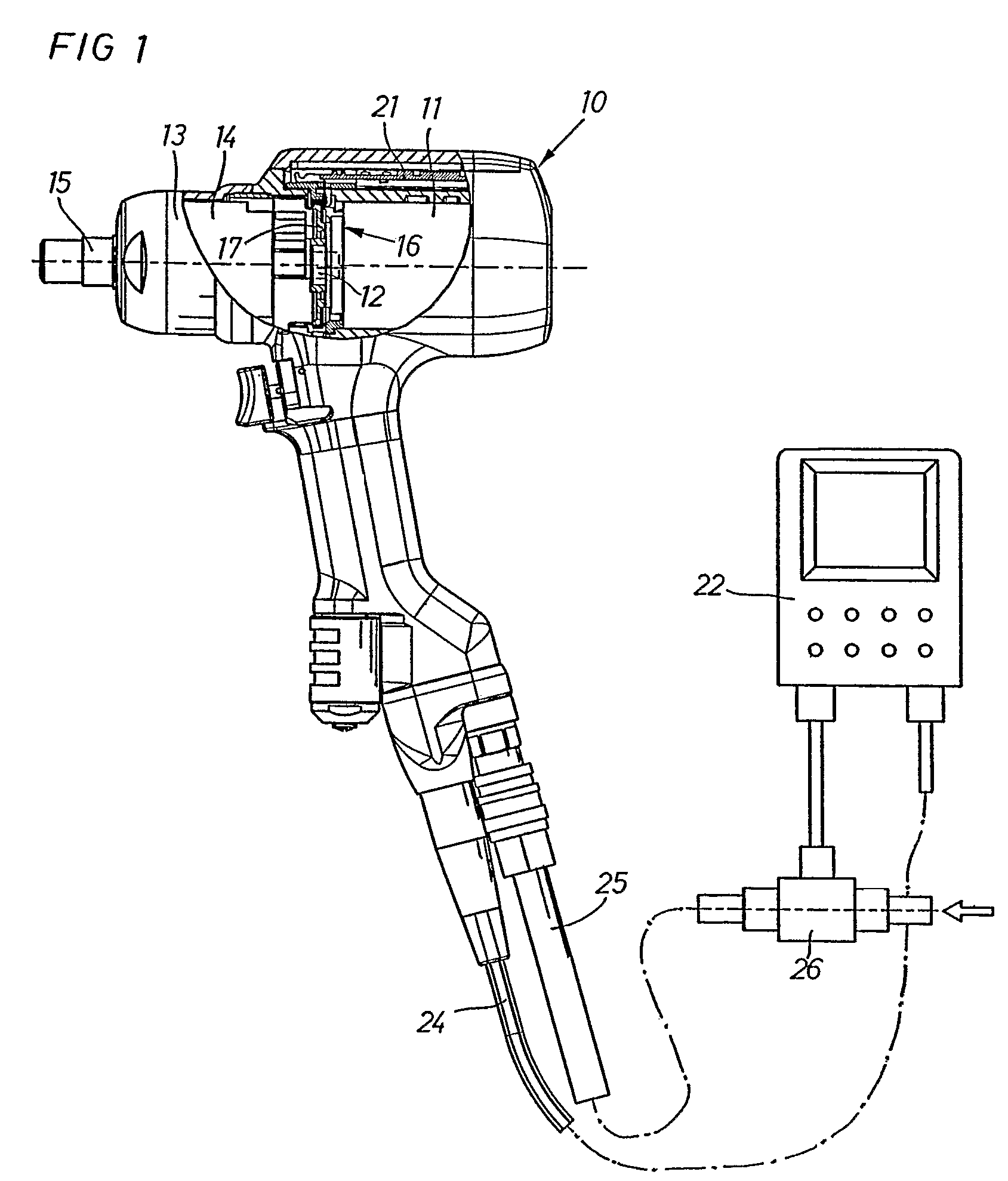
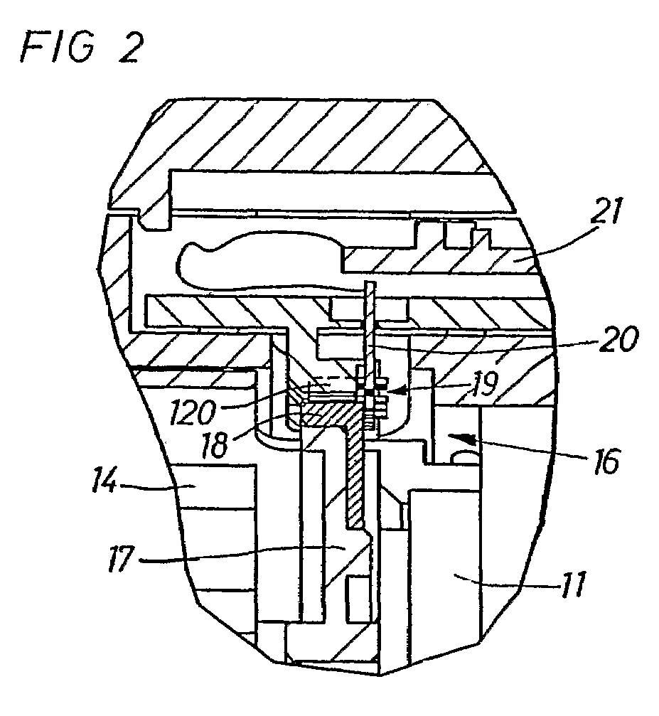
[0011]The power tool system illustrated in FIG. 1 comprises a pneumatic impulse wrench 10 including a motor 11 with a rotor 12, an impulse unit 13 including an inertia drive member 14 connected to the motor rotor 12, and an output shaft 15. The impulse wrench 10 further comprises an angular movement detecting device 16 which includes a disc 17 with a magnetised rim portion 18. The disc 17 is rigidly affixed to and co-rotating with the inertia drive member 14, and a stationary sensing device 19 located approximately to the magnetised rim portion 18 of the disc 17. The rim portion 18 is magnetised to provide a number of magnetic poles equally distributed along its periphery, and the sensing device 19 comprises sensor elements 120 carried on a connection board 20 and activated by the magnetic poles of the rim portion 18 to deliver electric signals in response to the movement of the disc 17. The connector board 20 is coupled to a circuit board 21 which carries a number of electronic com...


PUM


Abstract

A method and a power tool system are provided for performing screw joint tightening using a pneumatic torque impulse power tool that is controlled by a control unit. A torque magnitude and a torque growth are calculated based on signals delivered by an angle sensor, and pressurized air is supplied to the power tool via a flow regulating valve which is successively adjustable between zero and full power flow. The flow regulating valve is controlled by the control unit to deliver a reduced power air flow to the power tool before and during a first delivered impulse, and then to deliver full power flow until a certain torque magnitude or a percentage of a target torque level is reached, whereafter the air supply flow is again reduced until the target torque level is reached, and when the target torque level is reached the air flow is shut off.

Description

FIELD OF THE INVENTION[0001]The invention relates to a method and a power tool system for screw joint tightening, where the power tool system comprises a pneumatic impulse wrench, and a programmable control unit is arranged to control the operation of the impulse wrench according to a predetermined tightening strategy and in response to instantaneous values of one or more tightening parameters by regulating during tightening the pressure air supply to the impulse wrench.BACKGROUND OF THE INVENTION[0002]A problem concerned with pneumatically powered impulse wrenches is the difficulty to govern the tightening process accurately enough to ensure a correct and reliable pre-tensioning result. In a previously known impulse wrench system, described in U.S. Pat. No. 5,366,026, the output shaft of an impulse wrench is provided with a torque transducer for detecting the torque magnitudes of the delivered torque impulses, and a control unit for calculating a torque based clamping force and for...

Claims


Application Information

Patent Timeline
IPC IPC(8): G05B15/00B25B23/145
CPCB25B23/1453
Inventor FRIBERG, JOHN ROBERT CHRISTIANSCHOEPS, KNUT CHRISTIANSJOBLOM, TORBJORN RAFAELKARLBERG, ERLAND
Owner ATLAS COPCO TOOLS AB
Why Eureka
Try Eureka