Electrical connector assembly

a technology of electrical connectors and assembly parts, applied in the direction of fixed connections, coupling device connections, electric discharge lamps, etc., can solve the problems of high cost and complicated manufacturing process, and achieve the effect of reducing manufacturing costs

Inactive Publication Date: 2008-12-23
HON HAI PRECISION IND CO LTD
View PDF6 Cites 11 Cited by
  • Summary
  • Abstract
  • Description
  • Claims
  • Application Information

AI Technical Summary

Benefits of technology

[0006]Accordingly, one object of the present invention is to provide an electrical connector assembly which reduces the manufacture cost efficiently.
[0007]Another object of the present invention is to provide an electrical connector assembly having an enhanced mating force which makes a firm connection.

Problems solved by technology

However, said metal ears and contacts have different structures that requires to found different moulds respectively and different assembly processes, and this makes the manufacture process complicated with a high cost.

Method used


Image

  • Electrical connector assembly
  • Electrical connector assembly
  • Electrical connector assembly

Examples


Embodiment Construction

[0015]Reference will now be made to the drawing figures to describe the preferred embodiment of the present invention in detail.

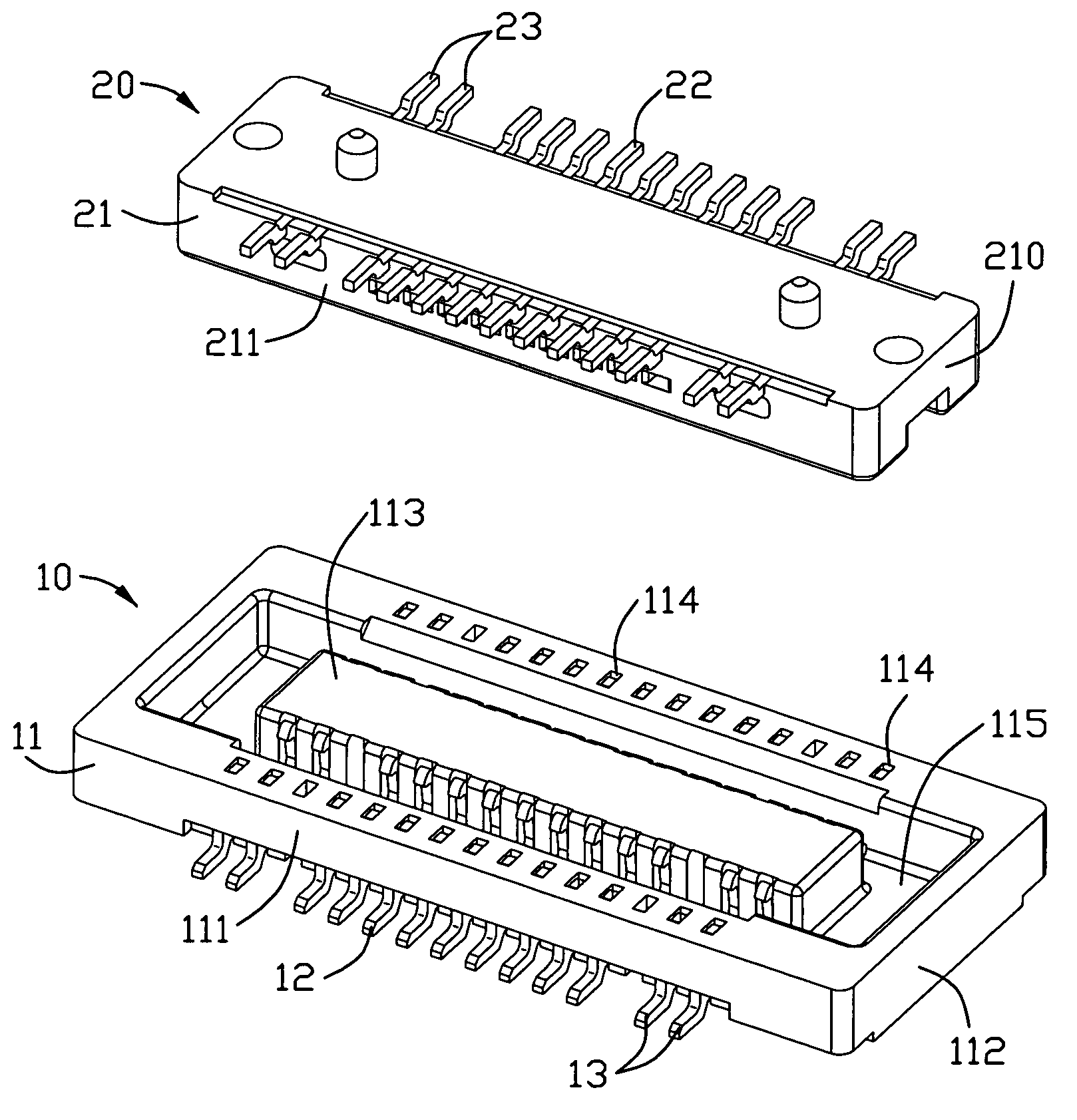
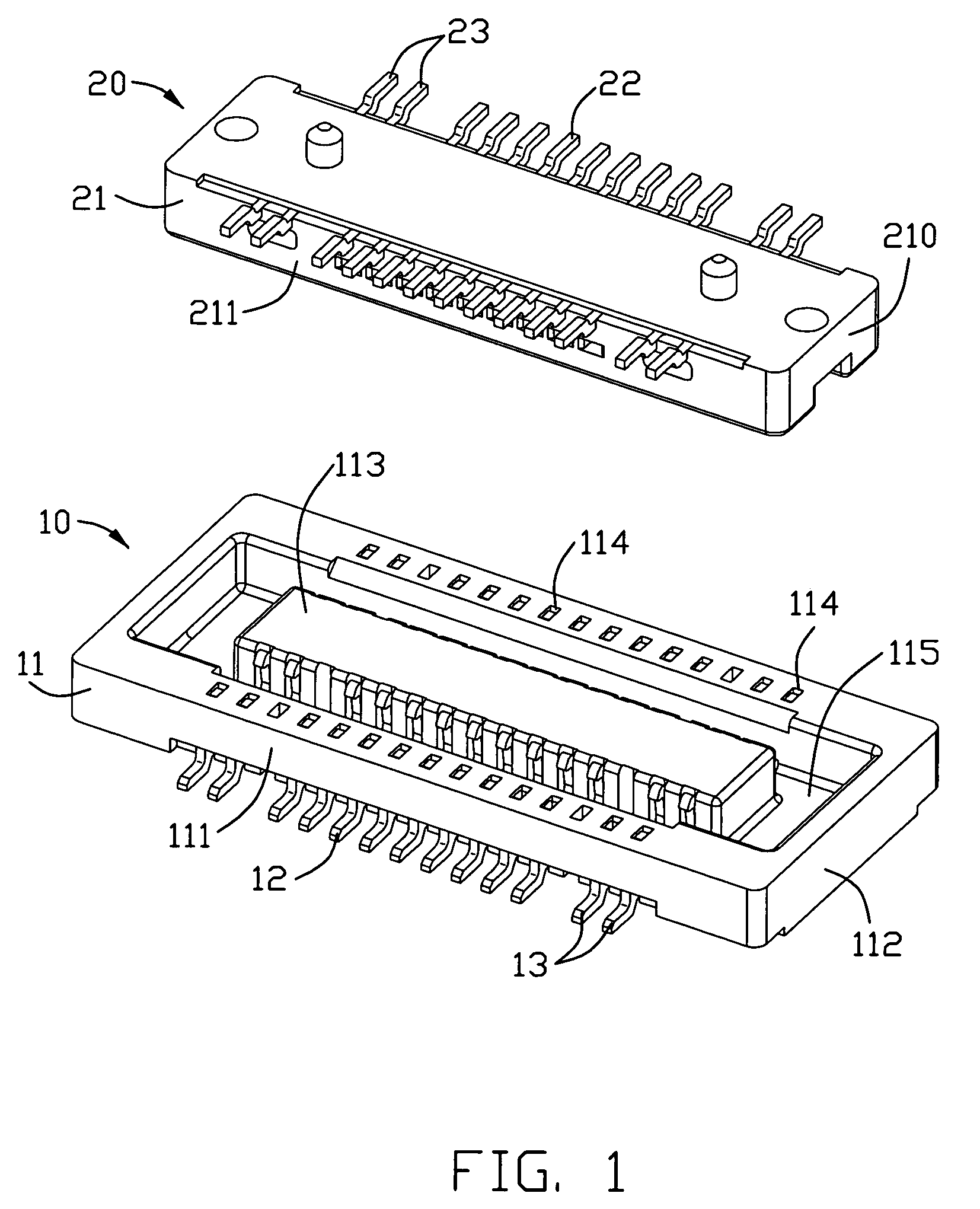
[0016]Referring to FIG. 1, an electrical connector assembly in accordance with the present invention is provided. The electrical connector assembly comprises a receptacle connector (10) and a plug connector (20) mating with said plug connector (10). Said receptacle connector (10) and said plug connector (20) are mounted on two printed circuit boards respectively.

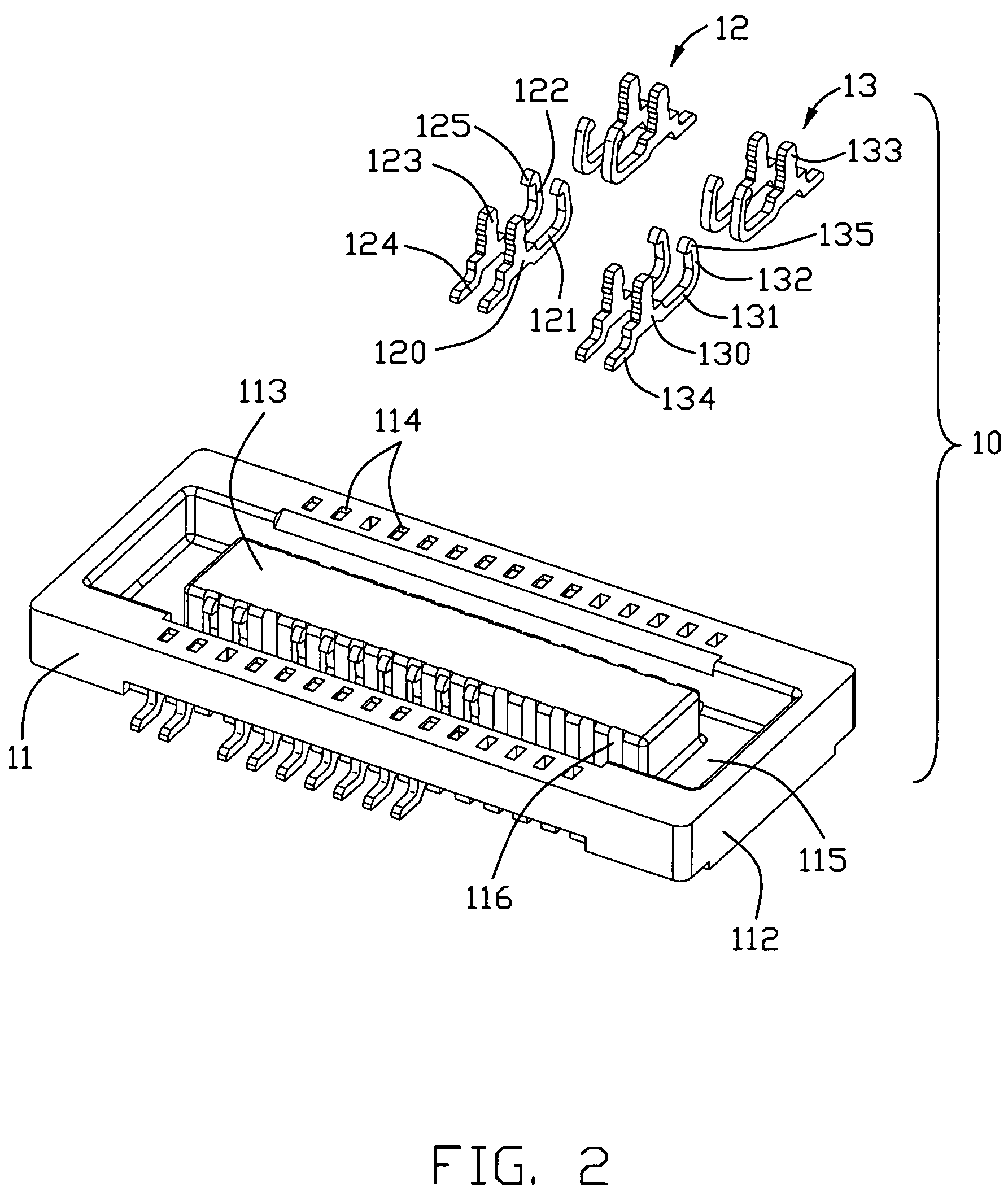
[0017]Referring to FIGS. 2 and 5, the receptacle connector (10) includes a first housing (11), a plurality of first contacts (12) retained in said first housing (11) and a pair of first metal ear (13) assembled on two sides of the first housing (11). Said first housing (11) has a longitudinal insulating body with a closed peripheral wall. The peripheral wall comprises a pair of sidewalls (111) and a pair of endwalls (112) connected with said sidewalls (111). Each sidewall (111) has a plurality of re...


PUM


Abstract

An electrical connector assembly comprises a receptacle connector and a plug connector engaged with said receptacle connector. Said receptacle connector comprises a first housing having a pair of longitudinal sidewalls, a plurality of first contacts retained in said sidewalls and at least one pair of first metal ears attached on said sidewalls. Said plug connector includes at least one pair of second metal ears engaged with said first metal ear. The first metal ear has a identical structure with said first contact and engages with the second metal ear so that the first metal ear and the first contact can share a same mound which reduces the cost.

Description

BACKGROUND OF THE INVENTION[0001]1. Field of the Invention[0002]The present invention relates to an electrical connector assembly, and more particularly to an electrical connector assembly connecting two printed circuit boards.[0003]2. Description of Related Art[0004]U.S. Pat. No. 6,645,005 discloses an electrical connector assembly including a plug connector and a receptacle connector engaged with each other. Both said plug connector and receptacle connector has a housing, a plurality of contacts and a pair of metal ears attached on two opposite ends of the housing. The metal ears include a pair of first metal ears and a pair of second metal ears respectively assembled on said plug connector and receptacle connector. The first metal ear of the plug connector has a mating arm extending upwardly with a protrusion on a surface thereon. Said second metal ear has a mating latch with a receiving portion on a surface thereon. Said protrusion of the first metal ear engages with said receiv...

Claims


Application Information

Patent Timeline
Patent Type & Authority Patents(United States)
IPC IPC(8): H01R12/00
CPCH01R12/57H01R13/6275H01R23/72H01R12/707H01R12/714H01R12/716
Inventor SHIU, GUO-JIUN
Owner HON HAI PRECISION IND CO LTD
Why Eureka
Try Eureka