Fast dynamic imaging protocol using a multi-head single photon emission computed tomography system

a computed tomography and dynamic imaging technology, applied in the field of nuclear imaging systems, can solve the problems of affecting the quality of the image obtained, further restricting the amount and activity of radiation available, and limited radioactive agents

Active Publication Date: 2008-12-23
THE CHILDRENS HOSPITAL OF PHILADELPHIA
View PDF15 Cites 46 Cited by
  • Summary
  • Abstract
  • Description
  • Claims
  • Application Information

AI Technical Summary

Problems solved by technology

For all nuclear imaging protocols, the amount of the radioactive agent is limited to that acceptable for the patient.
This places further restriction on amount and activity of radiation available for detection since the radiation also attenuates in the object, which in turn affects the quality of image obtained.
For humans, it is important to keep such time at a minimum because of danger of radiation to one's health and also the inconvenience of being in a confined environment.
However, these systems were not used for acquiring projections from both heads at the same time.
However, rotations described by patents to Hug et al. are just for pre-positioning the camera heads before acquiring data and not for imaging while in rotation.
Thus using these systems, it is possible to acquire planar dynamic images of, for example, kidneys (or VOI) or dynamic SPECT images of, for example, kidneys (or VOI) but it does not provide for acquiring images simultaneously.
Simultaneous acquisition of multiple views has been studied; however none of the studies disclose acquiring static (2D) and tomographic (3D) images at the same time.
This application does not disclose acquiring 2D and 3D data concomitantly during the study time.
The disadvantage of the planar images is that the counts from different organs may be superimposed.
Currently available 3D images do not provide sufficient clarity and have a significant amount of noise.
Using a tracer that has a fast disappearance rate, would not allow comparing static 2D and ECT 3D data if these studies were conducted sequentially and therefore require a repetitive exposure of a patient to an additional dose of radiation.

Method used


Image

  • Fast dynamic imaging protocol using a multi-head single photon emission computed tomography system
  • Fast dynamic imaging protocol using a multi-head single photon emission computed tomography system
  • Fast dynamic imaging protocol using a multi-head single photon emission computed tomography system

Examples


Embodiment Construction

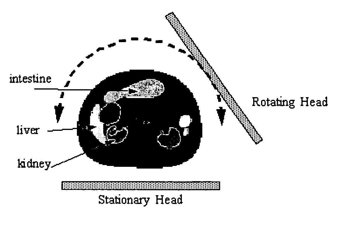
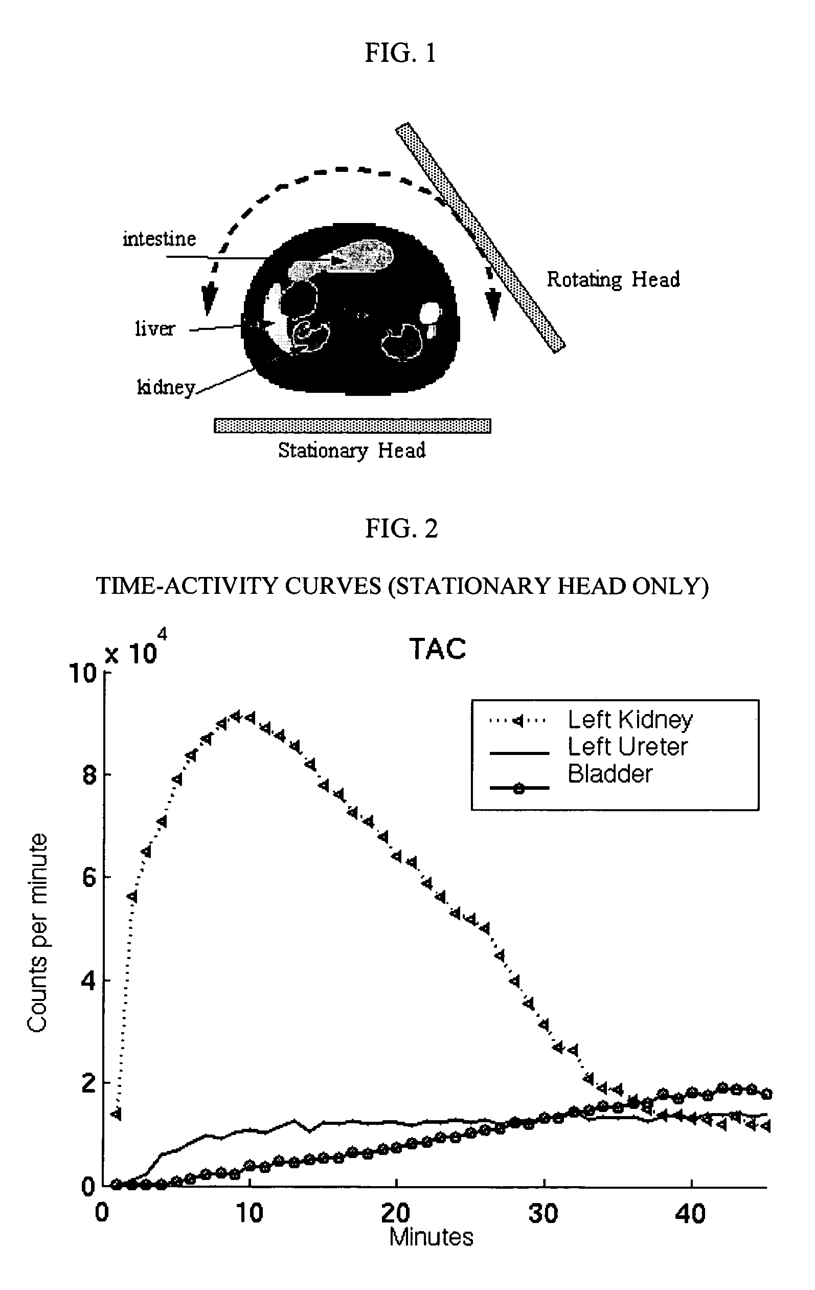
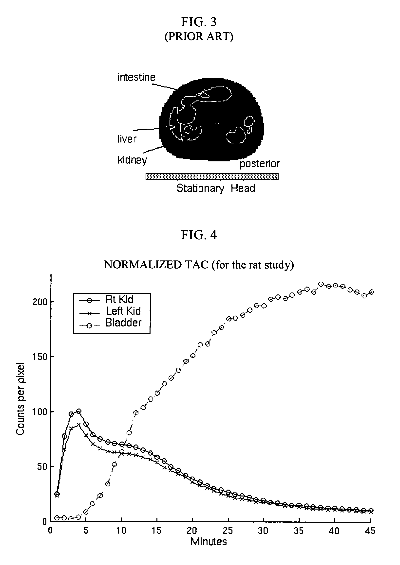
[0046]The invention was driven by a desire to develop a nuclear imaging systems capable of quantitative imaging that can provide better resolution obtained in a reasonable amount of time and without the use of additional radiation. The invention aims at improving the design and construction of the multi-head imaging single photon emission computed tomography (SPECT) system. This system can be used for screening natural (e.g., humans, animals, plants, etc.) and artificial objects, e.g., in nuclear medicine applications for screening or diagnosing. The invention is not limited to SPECT systems and can be used with PET and CT systems as well as other nuclear imaging systems.

[0047]The invention can be used for any applications where currently planar images are acquired, e.g., the study of obstructive uropathy, lung imaging, bone scans, imaging of the thyroid and brain. Now with multi-head scanners becoming very common the second and third head are literally lying idle or very little inf...


PUM


Abstract

An imaging system for acquiring multi-dimensional tomographic image data of an object, the imaging system having (1) a plurality of detectors to acquire image data, the detectors coupled to a supporting structure, wherein at least one of the detectors is adapted to move relative to the object during image data acquisition and wherein the detectors are adapted to rotate independently of each other, provided that image data from the detectors are collected concomitantly during a study time and (2) a data analyzer adapted to acquire and / or reconstruct the image data.

Description

BACKGROUND OF THE INVENTION[0001]1. Field of Invention[0002]This invention relates to a field of nuclear imaging systems and in particular to medical nuclear imaging systems involving multiple gamma cameras.[0003]2. Description of Related Art[0004]Nuclear imaging systems had been widely utilized to obtained anatomic and physiological information about patients at the organ and tissue level. Recent studies showed enhancement of an observation scale to provide details of various tissues and their functions at increasingly microscopic levels.[0005]Nuclear imaging systems emission computed tomography (ECT) and transmission computed tomography (CT). ECT is generally divided into two imaging techniques: single photon computed tomography (SPECT) and positron emission tomography (PET). ECT differs from CT in that in ECT the radiation source is a radioactive agent located inside the object (e.g., a patient) being imaged and in CT, the source of radiation is located outside of the object.[000...

Claims


Application Information

Patent Timeline
Patent Type & Authority Patents(United States)
IPC IPC(8): G01T1/166G01T1/161
CPCG01T1/1641A61B6/037G01T1/2985G01T1/166
Inventor CHARRON, MARTINBAL, GIRISH
Owner THE CHILDRENS HOSPITAL OF PHILADELPHIA
Why Eureka
Try Eureka