Methods for improving high frequency reconstruction

a high frequency reconstruction and high frequency technology, applied in the field of source coding systems, can solve the problems of reducing audio bandwidth, affecting the quality of speech analysis, and increasing the level of artefacts in the spectrum,

Active Publication Date: 2008-12-23
DOLBY INT AB
View PDF18 Cites 102 Cited by
  • Summary
  • Abstract
  • Description
  • Claims
  • Application Information

AI Technical Summary

Benefits of technology

[0010]A solution to the problems outlined above, and subject of this invention, is therefore the idea of a highly flexible HFR system that does not only allow to change the COF, but allows a much more flexible composition of the decoded / reconstructed spectrum by a frequency selective composition of different methods.

Problems solved by technology

The additional parameters could also be omitted, but as of today the quality reachable by such an approach will be worse compared to a system using additional parameters.
This has two main reasons:Traditional waveform codecs such as mp3 need to reduce the audio bandwidth for very low bitrates since otherwise the artefact level in the spectrum is getting too high.
A main problem with HFR is that an audio signal may contain components in higher frequencies which are difficult to reconstruct with the current HFR method, but could more easily be reproduced by other means, e.g. a waveform coding methods or by synthetic signal generation.
As there is no useful signal available in the low frequencies, the HFR method, based on extrapolating the lowband to obtain a highband, will not generate any signal.
This assumes, however, that it is possible to do so, which might not always be the case.
However, apart from that, the problem gets significantly more complicated even for parts of the spectrum within the reach of the core coder when considering more complex signals.
Adjusting the COF is not a solution in this case, as most of the gain achieved by the HFR method would diminish by using the core coder for a much larger part of the spectrum.

Method used


Image

  • Methods for improving high frequency reconstruction
  • Methods for improving high frequency reconstruction
  • Methods for improving high frequency reconstruction

Examples


Embodiment Construction

[0045]The below-described embodiments are merely illustrative for the principles of the present invention for improvement of high frequency reconstruction systems. It is understood that modifications and variations of the arrangements and the details described herein will be apparent to others skilled in the art. It is the intent, therefore, to be limited only by the scope of the impending patent claims and not by the specific details presented by way of description and explanation of the embodiments herein.

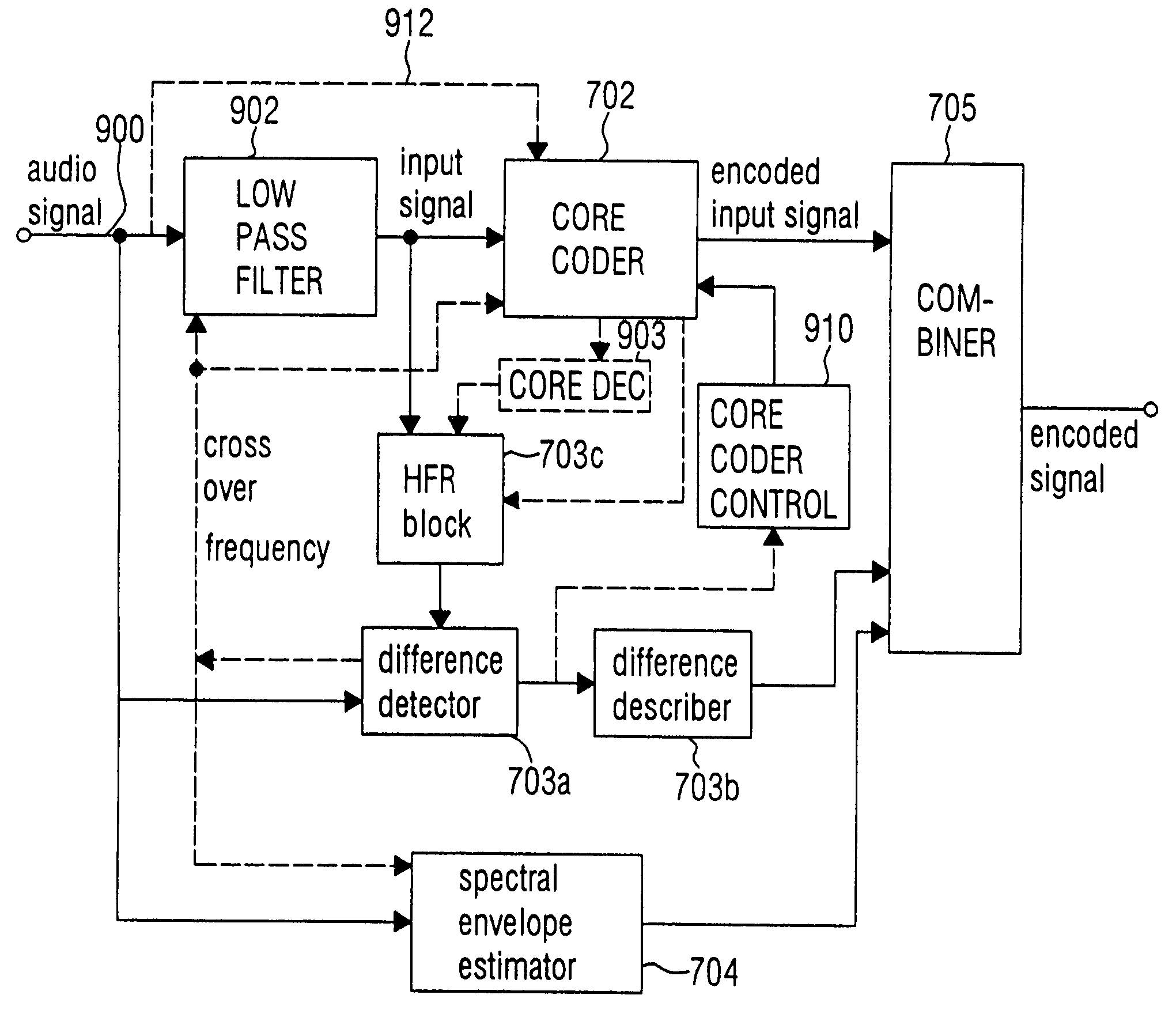
[0046]FIG. 9 illustrates an inventive encoder. The encoder includes a core coder 702. It is to be noted here that the inventive method can also be used as a so-called add-on module for an existing core coder. In this case, the inventive encoder includes an input for receiving an encoded input signal output by a separate standing core coder 702.

[0047]The inventive encoder in FIG. 9 additionally includes a high frequency regeneration block 703c, a difference detector 703a, a differ...


PUM


Abstract

The present invention proposes a new method and a new apparatus for enhancement of audio source coding systems utilizing high frequency reconstruction (HFR). It utilizes a detection mechanism (703a) on the encoder side to assess what parts of the spectrum will not be correctly reproduced by the HFR method in the decoder. Information on this is efficiently coded (703b) and sent to the decoder, where it is combined with the output of the HFR unit.

Description

CROSS REFERENCE TO RELATED APPLICATIONS[0001]This application claims priority under 35 U.S.C. 371 to International Application No.: PCT / EP02 / 13462, which was filed on Nov. 28, 2002, which claims a priority date of Nov. 29, 2001, and which is incorporated herein in its entirety by this reference thereto.TECHNICAL FIELD[0002]The present invention relates to source coding systems utilising high frequency reconstruction (HFR) such as Spectral Band Replication, SBR [WO 98 / 57436] or related methods. It improves performance of both high quality methods (SBR), as well as low quality copy-up methods [U.S. Pat. No. 5,127,054]. It is applicable to both speech coding and natural audio coding systems.BACKGROUND OF THE INVENTION[0003]High frequency reconstruction (HFR) is a relatively new technology to enhance the quality of audio and speech coding algorithms. To date it has been introduced for use in speech codecs, such as the wideband AMR coder for 3rd generation cellular systems, and audio cod...

Claims


Application Information

Patent Timeline
Patent Type & Authority Patents(United States)
IPC IPC(8): G10L19/00G10L21/00G10L19/02G10L19/07G10L19/24G10L21/02G10L21/038
CPCG10L21/038G10L19/0017G10L19/07G10L19/24G10L19/02G10L21/02G10L19/0204G10L19/028G10L19/06G10L19/093G10L19/0208G10L19/26G10L19/167G10L19/265
Inventor KJORLING, KRISTOFEREKSTRAND, PERHORICH, HOLGER
Owner DOLBY INT AB
Why Eureka
Try Eureka