Fluid cooled supercharger

a supercharger and liquid cooling technology, applied in the field of superchargers, can solve the problems of inability to heat the charge air, inability to meet the needs of customers, etc., and achieve the effect of improving the heat transfer

Inactive Publication Date: 2008-12-30
ACCESSIBLE TECHONOLOGIES
View PDF100 Cites 78 Cited by
  • Summary
  • Abstract
  • Description
  • Claims
  • Application Information

AI Technical Summary

Benefits of technology

[0009]In particular, a first aspect of the present invention concerns an improved air induction system in a powered vehicle including an engine. The improved air induction system broadly includes a supercharger and a supercharger support. The supercharger is mechanically driven by the engine to deliver compressed induction fluid to the engine. The supercharger includes a case that presents a compressor chamber in which induction fluid is compressed. The supercharger support is connected to the case to rigidly support the supercharger on the engine. The support includes a non-metal thermal-insulating portion. The thermal-insulating portion serves to thermally insulate the supercharger from conductive heating of the case by the engine.
[0012]A fourth aspect of the present invention concerns an air induction system for delivering compressed induction fluid to an engine, wherein the engine is cooled by a closed-loop engine coolant system. The air induction system broadly includes a centrifugal supercharger and a recirculating induction coolant system. The centrifugal supercharger is configured to be mechanically driven by the engine. The supercharger includes a case that presents a compressor chamber. The case includes a wall that defines a volute section of the compressor chamber. The supercharger further includes a rotatable impeller within the compressor chamber and is operable to compress induction fluid when powered by the engine. The case presents a compressor coolant passageway that is defined at least partly by the wall. The compressor passageway extends along at least part of the volute section of the compressor chamber. The recirculating induction coolant system fluidly connects to the compressor passageway and is operable to recirculate coolant through the compressor passageway. The case further includes a plurality of ridges projecting from the wall into the at least part of the volute section and thereby is configured to improve the transfer of heat from the compressed induction fluid to the coolant.

Problems solved by technology

Such heating of the air charge is undesirable because it reduces the air density and, thus, the overall mass air flow of the compressor.
Exhaust components within the engine compartment can also undesirably heat the charge air.
However, intercoolers add cost and reliability concerns to the induction system, as well as causing a significant pressure drop in the compressed induction fluid.

Method used


Image

  • Fluid cooled supercharger
  • Fluid cooled supercharger
  • Fluid cooled supercharger

Examples


Embodiment Construction

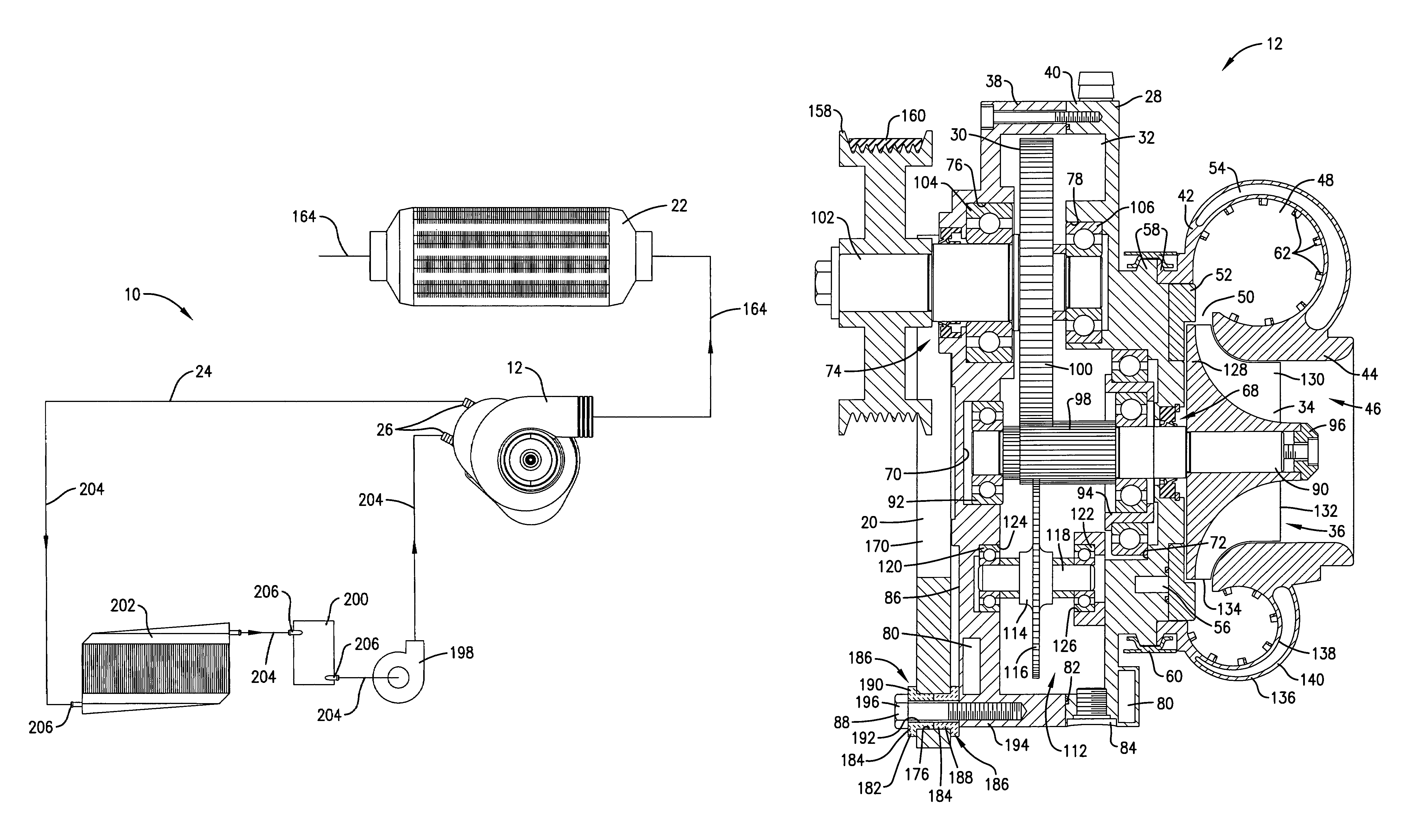
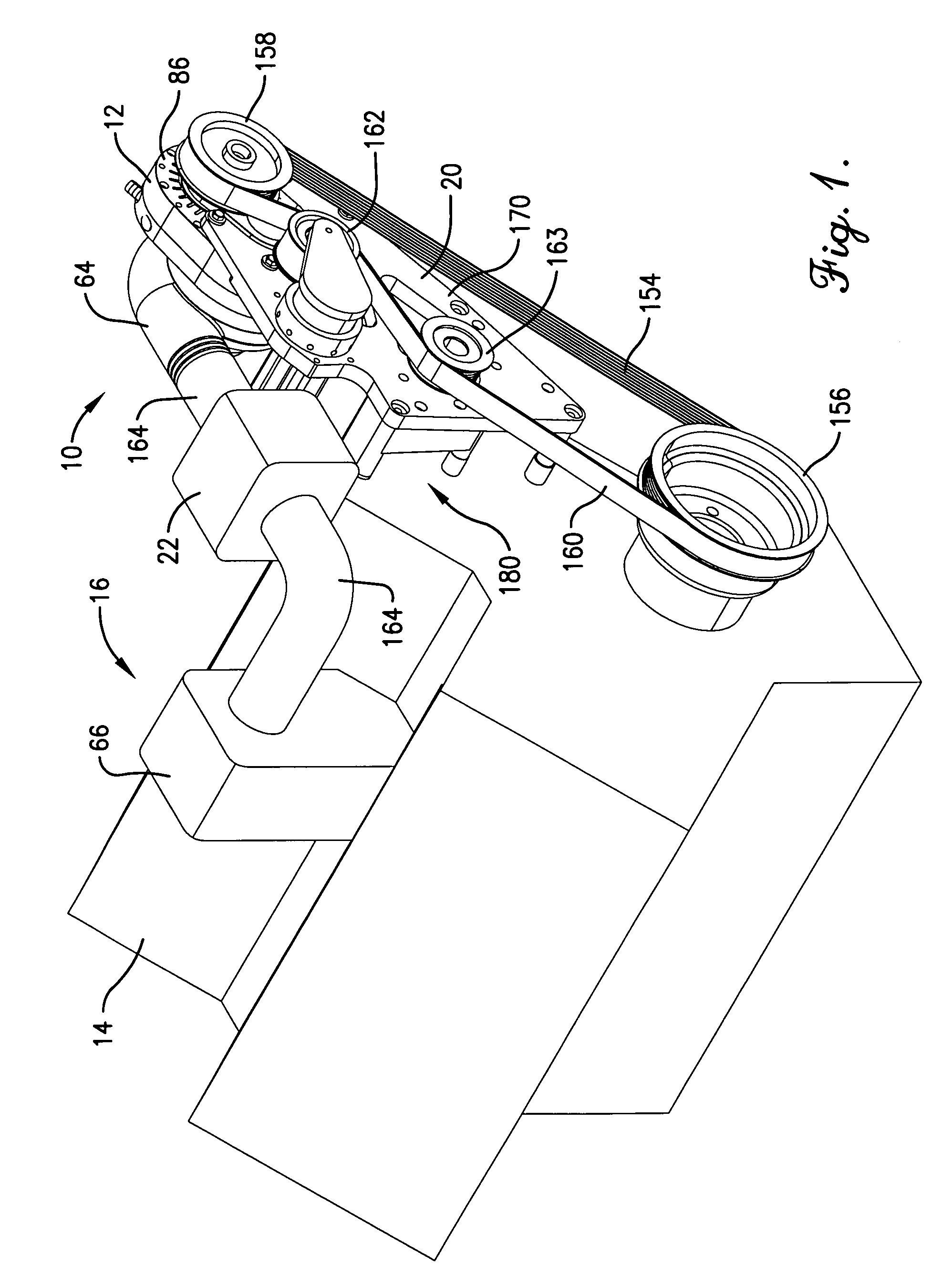
[0027]FIG. 1 illustrates a forced air induction system 10 utilizing a supercharger 12 constructed in accordance with a preferred embodiment of the present invention. The induction system 10 illustrated in FIG. 1 is shown in use with an internal combustion engine 14 to provide a supercharged engine unit 16. While the illustrated supercharger 12 is preferably a centrifugal supercharger, it is consistent with certain aspects of the present invention to employ other types of superchargers such as another type of dynamic compressor or a positive displacement compressor.

[0028]The supercharged engine unit 16 is further illustrated in use in a powered vehicle 18 as the vehicle's prime mover. The powered vehicle 18 could be an automobile, a motorcycle, a boat, or other similar device without departing from the principles of the present invention. Furthermore, the supercharged engine unit 16 of the present invention is equally applicable in other applications, such as power generation. Moreov...


PUM

PropertyMeasurementUnit
temperatureaaaaaaaaaa

Abstract

A forced air induction system for use with a powered vehicle is disclosed as including a centrifugal supercharger supported by the vehicle's engine and a recirculating induction coolant system that cools the supercharger and the compressed induction fluid provided by the supercharger. The induction coolant system operates by providing coolant to the supercharger and to an intercooler of the forced air induction system. The supercharger case includes internal passageways for cooling the transmission and compressor. The forced air induction system further includes spacers and radiant heat shields for rejecting heat transferred conductively and radiantly from the engine.

Description

RELATED APPLICATIONS[0001]This application claims the priority of Provisional Application Ser. No. 60 / 608,251, filed Sep. 9, 2004, entitled FLUID COOLED SUPERCHARGER, which is hereby incorporated by reference herein.BACKGROUND OF THE INVENTION[0002]1. Field of the Invention[0003]The present invention relates generally to the field of superchargers. More specifically, the present invention concerns a supercharger for providing induction fluid to an engine, where the supercharger is thermally insulated from the engine. The present invention also concerns an air induction system for an engine that includes a supercharger and a coolant system dedicated to the air induction system.[0004]2. Discussion of Prior Art[0005]Superchargers in air induction systems generally operate at temperatures above ambient. In particular, it is known in the art that the compression provided by a supercharger increases the temperature of the air charge as well as its pressure due to thermodynamic effects. Su...

Claims


Application Information

Patent Timeline
Patent Type & Authority Patents(United States)
IPC IPC(8): F02B33/00B23K31/00F01D1/02F01D25/28F02B39/04F16M11/00F16M13/00F04D29/58F02B39/00F01D9/00F02B29/04
CPCF02B33/40F02B39/00F02B39/04F04D13/12F04D25/16F04D29/545F04D29/5833F02B29/04F02B39/16F05B2220/40F04D29/4206F04D29/584
Inventor JONES, DANIEL W.CARLSON, MICHAEL A.
Owner ACCESSIBLE TECHONOLOGIES
Why Eureka
Try Eureka