Diffuser having optical structures

a technology of optical structure and diffuser, which is applied in the field of diffusers, can solve the problems of poor light utilization, uneven luminance of light output, and thus reduced light transmittance, and achieve the effect of expanding the space distribution of light sources

Active Publication Date: 2008-12-30
AU OPTRONICS CORP
View PDF9 Cites 4 Cited by
  • Summary
  • Abstract
  • Description
  • Claims
  • Application Information

AI Technical Summary

Benefits of technology

[0007]In light of the above drawbacks in prior art, it is an objective of the present invention to provide a diffuser that extends space distribution of light sources.
[0009]It is a further objective of the present invention to provide a diffuser that generates a uniform light output.
[0010]The present invention discloses a diffuser used in a backlight module comprising a plurality of light sources, which generates a uniform light output effectively. The diffuser according to the present invention mainly includes a transparent substrate and a plurality of optical structures. The transparent substrate has an entrance surface and an exit surface, and the plurality of optical structures is disposed on the exit surface. Each optical structure is dented from the exit surface to the interior of the transparent substrate and forms a refractive convex within the transparent substrate, and each refractive convex corresponds to one of the plurality of light sources. The included angle between the tangent to the refractive convex edge and the normal to the exit surface lead an incident light ray from the light sources to refract and deviate from the normal to the refractive convex through the refractive convex.

Problems solved by technology

However, when LCD panels use LEDs as the light sources, there will be frequent occurrence of uneven luminance of the light output.
However, in the abovementioned light paths, light absorption is inevitable due to inherent and chemical particle properties of the materials, and light transmittance is thus reduced.
In the abovementioned structure, part of the light is wasted for observers from a constant distance as light scattering is random, and thus may result in poor light utilization.
In addition, the chemical processes of the manufacturing method of the diffusion films are more time-consuming, thus the associated cost is relatively higher.

Method used


Image

  • Diffuser having optical structures
  • Diffuser having optical structures
  • Diffuser having optical structures

Examples


Embodiment Construction

[0026]Numerous specific details are set forth in the following description in order to provide a thorough explanation of various embodiments of the present invention, and the accompanying drawings are provided for illustration purposes only and are not intended to limit the present invention.

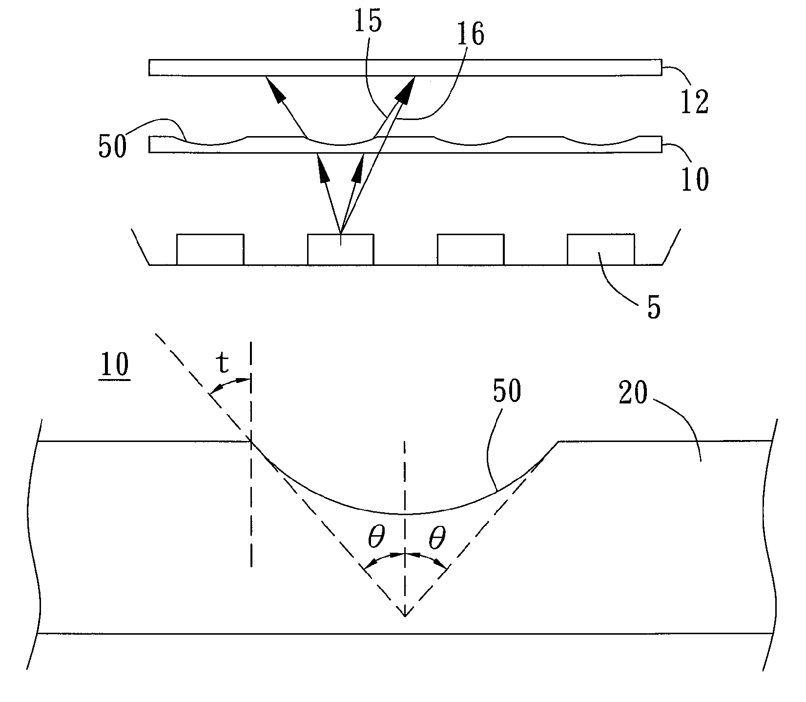
[0027]The present invention provides a diffuser for a backlight module to redistribute light intensity by using the highest-intensity angular energy through the diffuser of the present invention in order to produce light refraction and to re-add up a greater-angle weaker energy not passing through the diffuser to obtain a new angular energy distribution. Therefore, space distribution of the point spread function (PSF) of the original light sources can be extended, and a desired uniform light output is achieved after the backlight generated by the point light sources or linear light source passes through the diffuser in accordance with the present invention.

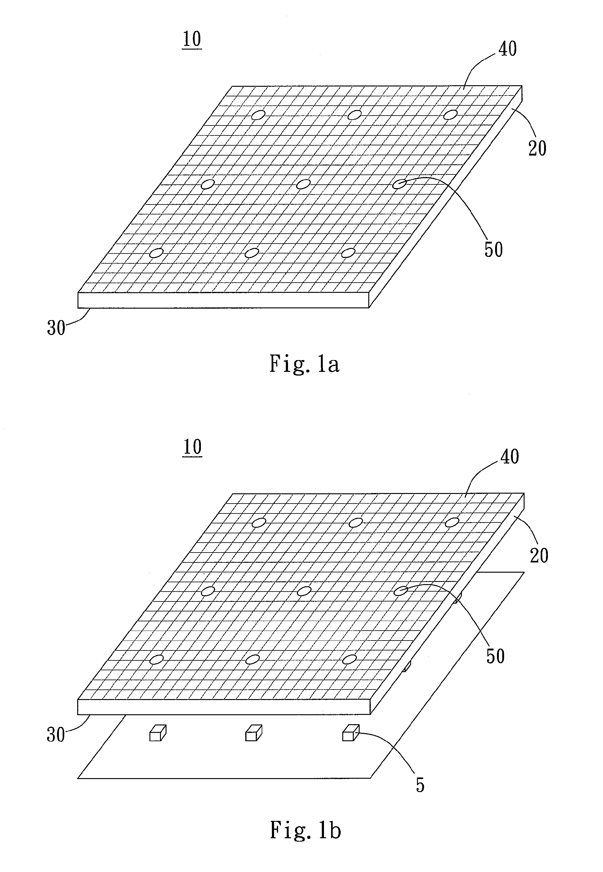
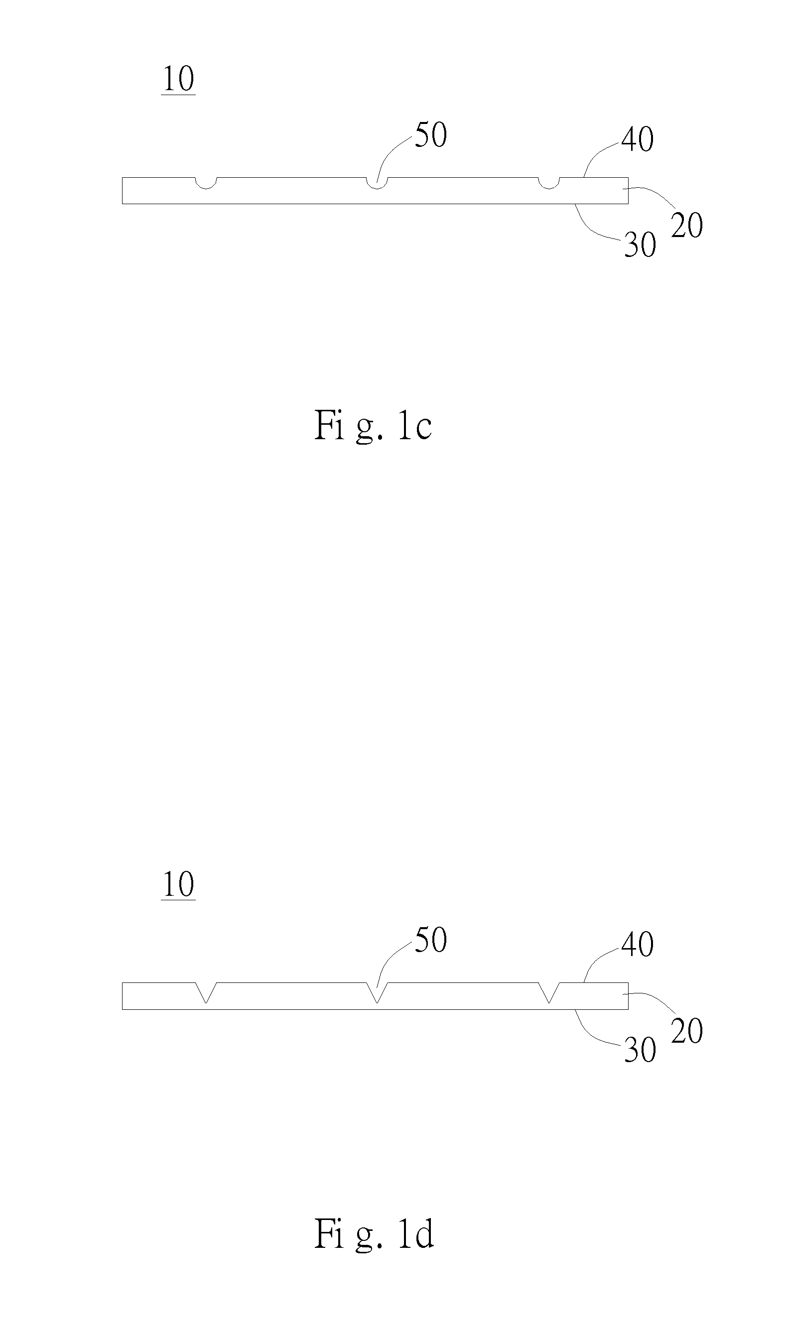
[0028]As shown in FIG. 1a, the diffuser...


PUM


Abstract

A diffuser used in a backlight module including a plurality of light sources is disclosed. The diffuser according to the present invention makes a uniform light output. The diffuser includes a transparent substrate and a plurality of optical structures. The transparent substrate has an entrance surface and an exit surface. The plurality of optical structures is disposed on the exit surface, each optical structure is dented from the exit surface to the interior of the transparent substrate and forms a refractive convex within the transparent substrate, and each refractive convex corresponds to one of the plurality of the light sources. The maximum value of the included angle between the tangent to the refractive convex edge and the normal to the exit surface is smaller than 30 degrees, such that an incident light ray from the light sources refracts and deviates from the normal to the refractive convex through the refractive convex.

Description

BACKGROUND OF THE INVENTION[0001]1. Field of the Invention[0002]The present invention relates generally to diffusers, and more particularly to a diffuser which outputs a uniform light used in a backlight module.[0003]2. Description of the Prior Art[0004]Since liquid crystal displays (LCD) are not self-luminous display devices, backlight sources are needed to provide light sources with sufficient brightness and uniform light output to show images properly. Current backlight sources mostly use light emitting diodes (LEDs) and cold cathode fluorescent lamps (CCFL) as the main luminous elements. LEDs have numerous advantages, such as wide color variety, low power consumption, small volume, low pollution produced, high reliability and great module flexibility, and thus have become increasingly important. However, when LCD panels use LEDs as the light sources, there will be frequent occurrence of uneven luminance of the light output. In order to distribute point light sources or linear li...

Claims


Application Information

Patent Timeline
Patent Type & Authority Patents(United States)
IPC IPC(8): F21V33/00
CPCG02B5/0215G02B5/0278G02F1/133606
Inventor PENG, CI-GUANGWANG, CHIH-LINLIAO, JING-HUANTSAI, SHAU-YU
Owner AU OPTRONICS CORP
Why Eureka
Try Eureka