Dual access spike for infusate bags

a technology of infusate and spike, which is applied in the field of double access spike for infusate bags, can solve the problems of short-circuit flow that does not, and achieve the effect of increasing the cross-sectional area and easing the force of the connector

Active Publication Date: 2008-12-30
NXSTAGE MEDICAL INC
View PDF49 Cites 75 Cited by
  • Summary
  • Abstract
  • Description
  • Claims
  • Application Information

AI Technical Summary

Benefits of technology

[0006]Various features of the double access spike provide for reliable insertion and use for recirculation. For example, the tip may be beveled to provide a sharp point that eases the piercing of the membrane. The outlet opening may be formed in a rounded or beveled surface located at the very tip. In addition, the inlet opening may be provided on a second beveled surface whose edges are rounded to allow it to pass through the membrane easily. In a preferred configuration, the beveled surface is conical to ease insertion. Another feature is that the lower portion is made substantially larger than the upper portion, the latter being so narrow as to not make a tight fit into the port. This requires that the spike be inserted all the way into the port to obtain a seal. The transition to a wide diameter base of the spike may be made an abrupt one and the inlet opening located sufficiently far away from the base to guarantee its placement in the larger volume of the bag. Other features and variations on the invention will be apparent from the detailed description below.
[0008]In this embodiment, the body may have a base shaft substantially coaxial with the elongated shaft and located at the base, the base shaft having a diameter large enough to provide a compression seal with an opening of the elongated access neck. A transition portion of the body between the elongated shaft and the base shaft may be characterized by a progressively increasing cross-sectional area that is effective to ease a forcing of the connector through any obstacles in the elongated extension. The elongated shaft may have a diameter that is too small to provide a compression seal with an opening of the elongated access neck. The outlet opening may be located at the base. Where the body has a base shaft substantially coaxial with the elongated shaft and located at the base, the base shaft may have a diameter large enough to provide a compression seal with an opening of the elongated access neck. In such as, the elongated shaft may have a diameter that is too small to provide a compression seal with an opening of the elongated access neck. This ensures the connector is inserted well into the elongated access extensions of some fluid containers, such as fluid bags used for infusible fluids.
[0009]According to another embodiment, the invention is a connector for use with fluid containers having access ports with elongated necks. The connector has a body constructed for coupling to a fluid container, a first fluid passage in the body, a second fluid passage in the body that does not communicate with the first fluid passage. A first assembly communicating with the first fluid passage and including a first fitting to releasably couple the first fluid passage to an outlet of a fluid circuit and to convey fluid only through the first fluid passage is also provided. A second assembly communicates only with the second fluid passage and includes a second fitting to releasably couple the second fluid passage to an inlet of the fluid circuit. As a result, fluid can be circulated through the fluid container in a loop that includes the fluid circuit to collect in the fluid source air residing in the fluid circuit. The body has an elongated portion sufficiently long to ensure an outlet of the first fluid passage can reach into the fluid container and beyond a neck of the container.
[0010]In this embodiment, one end of the connector body may be tapered to form a spike. At least one of the first and second assemblies may include a luer fitting. At least one of the first and second assemblies may include an in-line clamp. The body may include a distal end communicating with the fluid source, wherein the first and second fluid passages each exits the distal end, and wherein the first fluid passage exits the distal end of the body at a higher gravity height that the second fluid passage exits the distal end. The base of the body near the releasable connectors may be wider than near the tip such that if the connector is not fully inserted in a port, the fluid will leak. This configuration may help to ensure the connector is fully inserted so the outlet is well within the container.

Problems solved by technology

One problem that may arise in connection with the spike discussed in the above application is that some fluid bags have long tube-shaped ports which surround the entire length of the spike so that the inlet and outlet openings both lie in a narrow tubular channel.
The confinement of the outlet to the narrow channel can cause short-circuit flow that does not permit bubbles to settle out of the flow injected into the reservoir.

Method used


Image

  • Dual access spike for infusate bags
  • Dual access spike for infusate bags
  • Dual access spike for infusate bags

Examples


Embodiment Construction

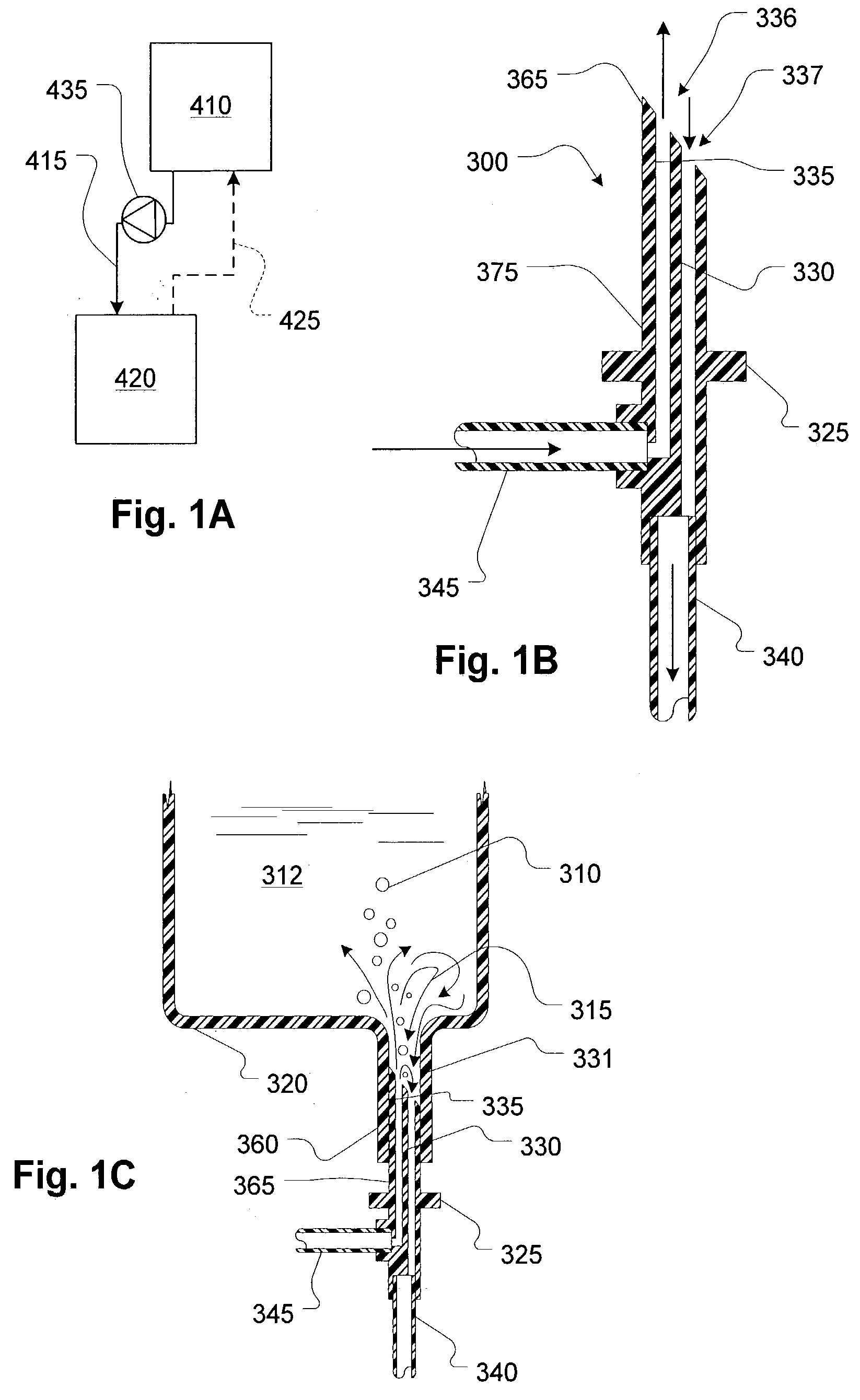
[0030]Referring to FIG. 1A, a fluid reservoir 410 supplies fluid via a supply channel 415 to a fluid circuit represented schematically at 420. The fluid circuit 420 may be a blood treatment systems such as dialysis or hemofiltration. Fluid may be conveyed with the assistance of a pump 435, which, although shown separately may form part of the fluid circuit 420. The fluid reservoir 410 may be connected temporarily to allow a return flow 425 and may employ two accesses to the reservoir 410.

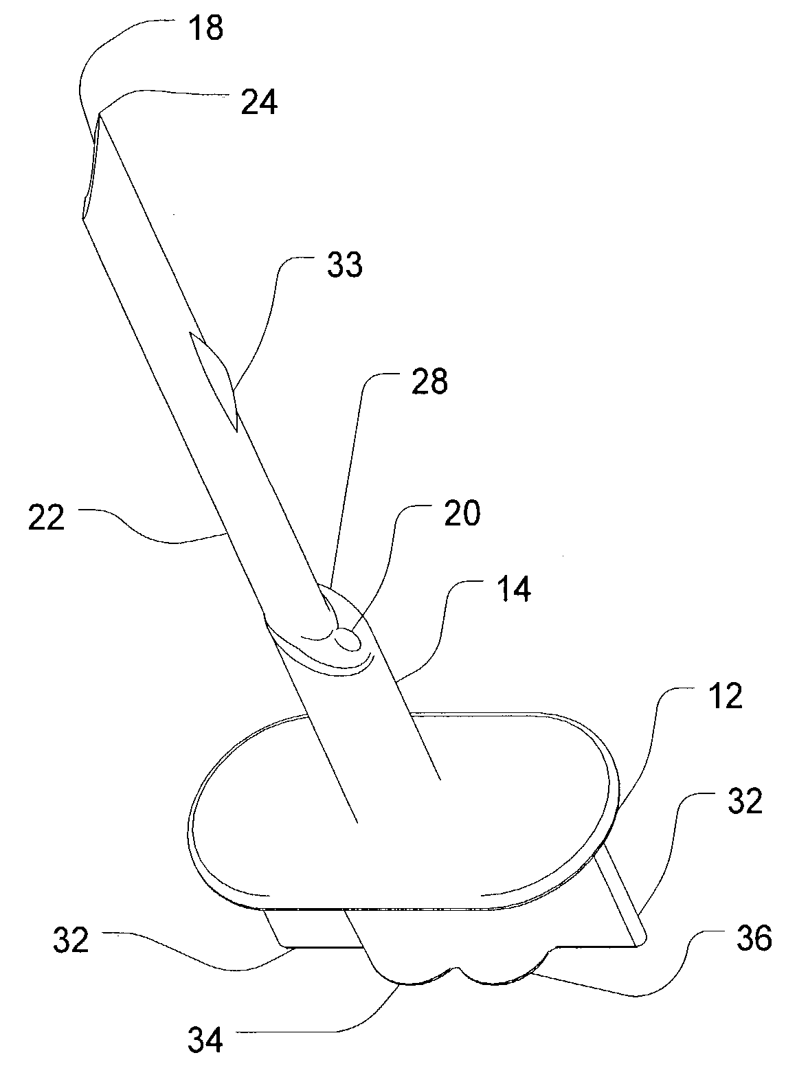
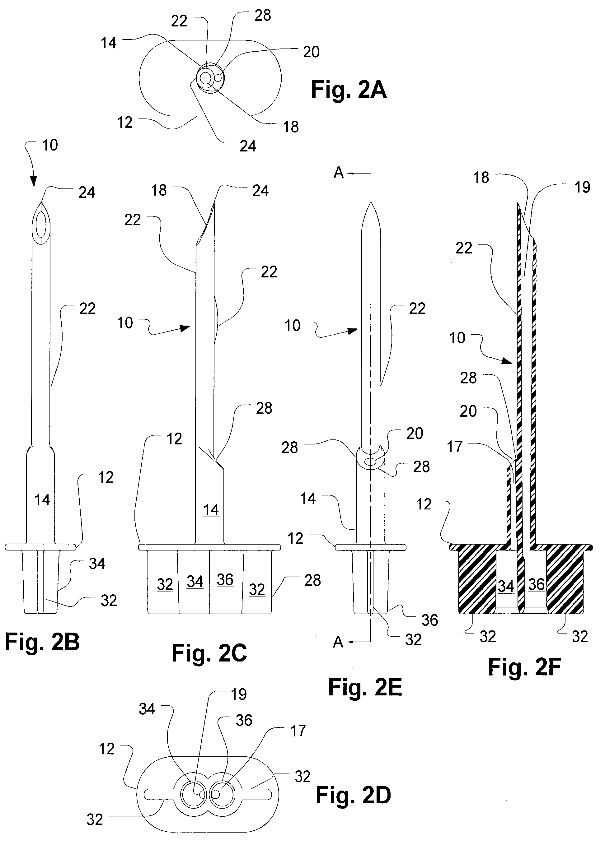
[0031]Referring now to FIG. 1B, a spike shown generally at 300, has a pointed tip 365 and inlet and outlet openings 336 and 337, respectively, near the tip 365. A handle portion 325 facilitates insertion of the spike 300 into a container port (not shown in this figure, but described below). An inlet tube 345 supplies fluid through a channel 335 to the inlet opening 336. An outlet tube 340 draws fluid through a channel 330 from the outlet opening 337. An elongated shaft 375 has a uniform diameter for...


PUM


Abstract

A port spike for medical fluid containers, such as infusate bags, for example, provides two ports to permit recirculation of fluids within the container. The recirculating flow allows bubbles to settle out which can't happen effectively if the flow is sucked out immediately after entering the container. The spike provides two openings inside the container which prevent such short-circuit flow by ensuring that fluid entering the container is not greatly affected by the suction zone of the flow leaving the container.

Description

FIELD OF THE INVENTION[0001]The invention generally relates to access used for providing two openings to a fluid container, for example, an infusible fluid bag such as saline.BACKGROUND OF THE INVENTION[0002]Air needs to be eliminated from many kinds of fluid circuits. For example, in extracorporeal blood circuits, air in replacement fluid that is injected into a patient can be hazardous. Typically; drip chambers are used in such circuits because these may serve as air traps. Another device is air-trapping filters. There exists a need for effective and convenient techniques for removing air from such circuits.SUMMARY OF THE INVENTION[0003]The invention provides systems and devices for handling air in a fluid processing circuit. U.S. patent application Ser. No. 09 / 905,171, incorporated by reference as if fully set forth herein in its entirety, describes systems for priming a replacement fluid circuit of a hemofiltration machine by recirculating fluid through a replacement fluid reser...

Claims


Application Information

Patent Timeline
Patent Type & Authority Patents(United States)
IPC IPC(8): A61B19/00A61M5/162A61M5/32A61M5/36
CPCA61M5/162A61M5/36
Inventor BRUGGER, JAMESBUCKLER, KENNETH E.
Owner NXSTAGE MEDICAL INC
Why Eureka
Try Eureka