Method for the production of structural components from fiber-reinforced thermoplastic material

a technology of thermoplastic material and fiber reinforcement, applied in the direction of superstructure subunits, lamination, domestic articles, etc., can solve the problems of inability to meet the requirements of structural components, limited possible shaping and applications, and still manifest essential disadvantages with respect to efficient production, reproducibility, and development of an integrated continuous fiber load-bearing structur

Active Publication Date: 2008-12-30
WEBER TECH
View PDF11 Cites 12 Cited by
  • Summary
  • Abstract
  • Description
  • Claims
  • Application Information

AI Technical Summary

Benefits of technology

[0005]Also disclosed are advantageous further developments of the invention with particular advantages with respect to efficient cost-effective series production capable of being automated, with short cycle times as well as optimum alignment and forming of the continuous fiber reinforcing structures with improved mechanical characteristics. With this, it is possible to produce light structural components for a large number of applications, e.g., for means of transportation, vehicles and vehicle components with load-bearing functions and this in a simple and precise manner.

Problems solved by technology

Known methods for the production of such structural components in most cases utilise plane continuous fiber reinforcements, e.g., in the form of semi-finished fabric products or with a sandwich structure, which, however, are very limited with respect to possible shaping and applications.
Also these known processes, however, still manifest essential disadvantages with respect to efficient production, reproducibility and a defined development of an integrated continuous fiber load-bearing structure.
In this manner it is not possible to produce a defined, single piece structural component, which can be made in a single press step and which comprises an integrated, precisely defined, optimally positioned and shaped, load-optimised continuous fiber reinforcing structure.

Method used


Image

  • Method for the production of structural components from fiber-reinforced thermoplastic material
  • Method for the production of structural components from fiber-reinforced thermoplastic material
  • Method for the production of structural components from fiber-reinforced thermoplastic material

Examples


Embodiment Construction

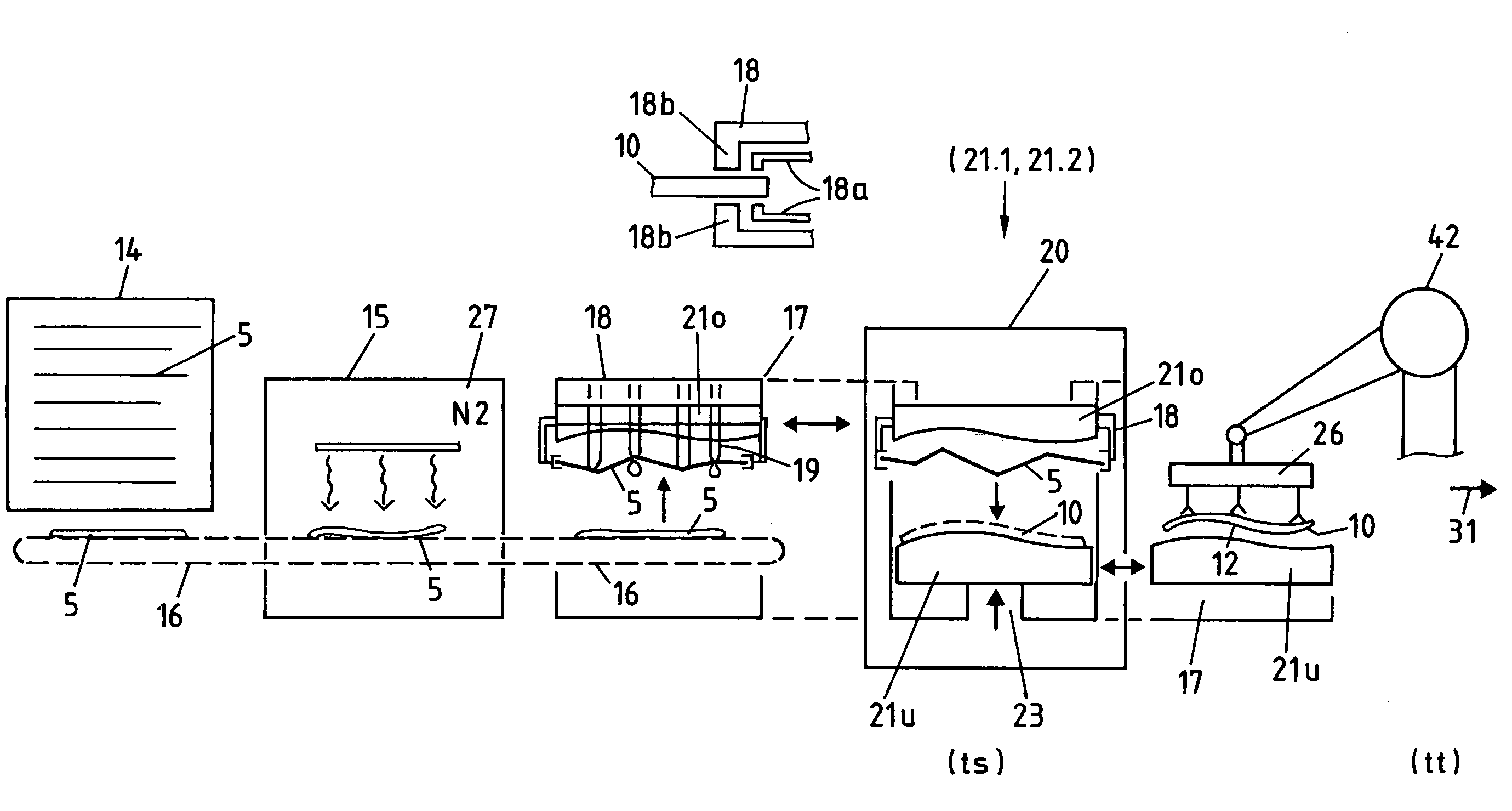
[0027]FIG. 1 schematically illustrates the method according to the invention for the production of structural components out of long-fiber thermoplastic material (LFT) with integrated continuous fiber (CF)-reinforcements in a single stage LFT-pressing process by means of shock-cooling and CF-profile compression moulding in its sequence.

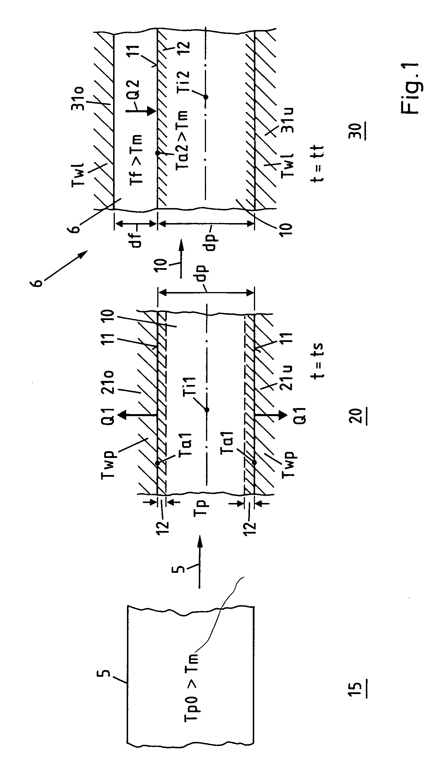
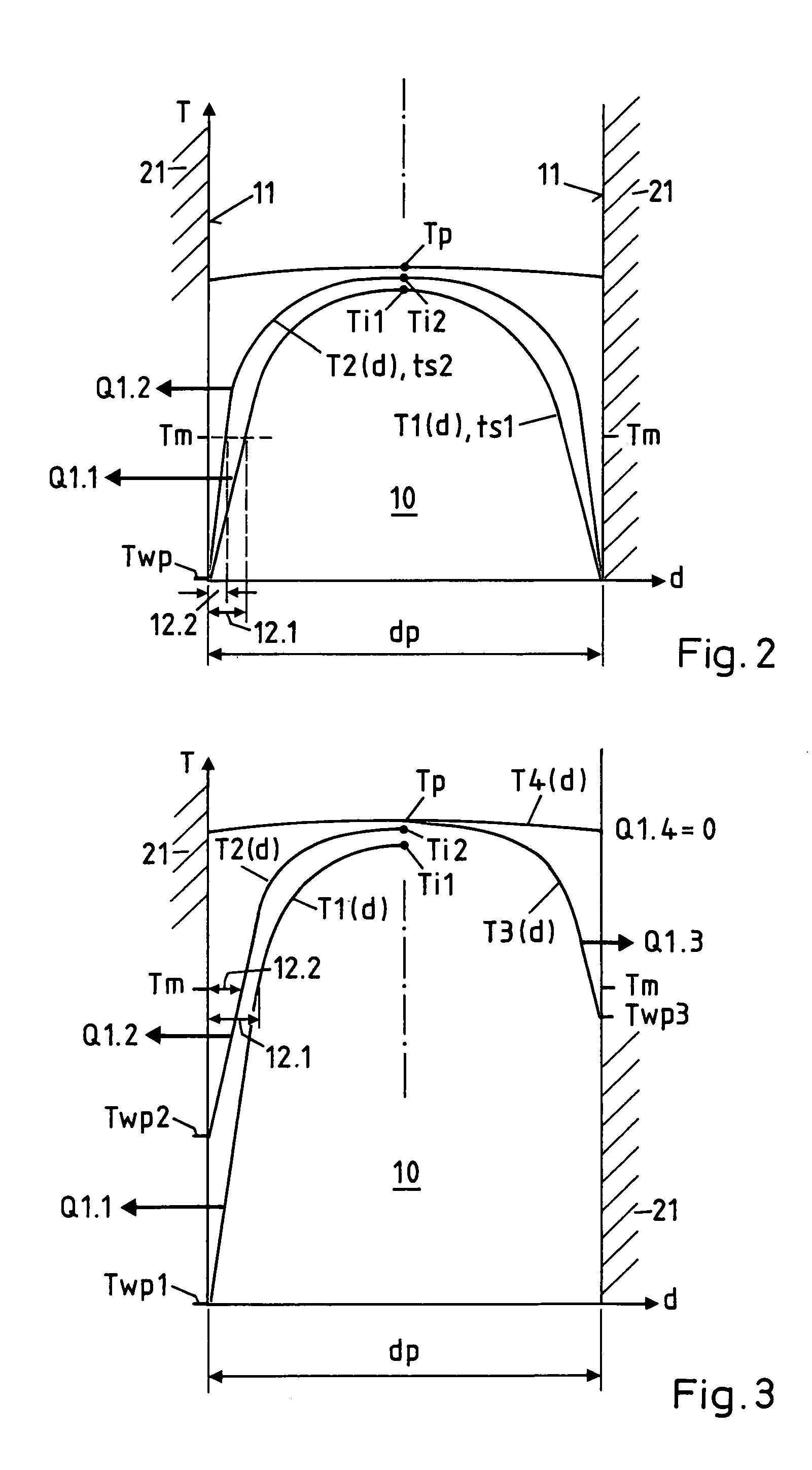
[0028]In a heating station 15 impregnated, particularly, pre-consolidated CF-tapes or bands 5 are completely melted to a practically homogeneous temperature Tp0, which is selected to be well above the melting point Tm, and subsequently transferred into a two-part profile tool 21 (here in 21u where “u” means “under”) of a CF-profile forming station 20. Here the CF-tapes 5 with an input temperature Tp are formed into a chosen CF-profile 10 by means of pressing for a short time during a precisely defined shock-cooling period ts. During this form pressing and shock-cooling, a shock-cooled, dimensionally stable thin casing layer 12 is formed through the co...


PUM

PropertyMeasurementUnit
lengthaaaaaaaaaa
thicknessaaaaaaaaaa
thicknessaaaaaaaaaa

Abstract

The method enables the series production of light structural components out of long-fiber thermoplastic material (LFT) with integrated continuous fiber (CF)-reinforcements in a single stage LFT-pressing step. In this, CF-tapes (5) are melted open and transferred into a profile tool (21) of a CF-profile forming station (20), there are pressed for a short time period and shaped into the required CF-profile (10). In doing so, by means of contact with the thermally conditioned profile tool (21) on the profile surface (11) a shock-cooled, dimensionally stable, thin casing layer (12) is formed and the inside of the CF-profile remains melted. Following a defined short shock-cooling period (ts), the CF-profile (10) is transferred into an LFT-tool (31) and pressed together with an introduced molten LFT-mass (6). In doing so, the casing layer (12) is melted open again on the surface (11) and is thermoplastically bonded together with the surrounding LFT-mass.

Description

BACKGROUND[0001]The invention is related to a method for the production of structural components from long fiber thermoplastic with integrated continuous fiber reinforcements as well as to an installation for the production of structural components of this kind. Known methods for the production of such structural components in most cases utilise plane continuous fiber reinforcements, e.g., in the form of semi-finished fabric products or with a sandwich structure, which, however, are very limited with respect to possible shaping and applications.[0002]From international patent application publication WO99 / 52703 a method for the production of structural components is known, in the case of which molten continuous fiber strands are deposited on top of one another, so that they form a coherent load-bearing structure with plane joints and are pressed in a tool together with a forming mass reinforced with long fibers. Also these known processes, however, still manifest essential disadvanta...

Claims


Application Information

Patent Timeline
Patent Type & Authority Patents(United States)
IPC IPC(8): B29C45/14B29C43/18B29C70/06B29C70/34B29C70/46B29D99/00
CPCB29C70/46B60N2/686B62D25/085B62D29/041B60R19/03Y10T428/24994Y10T428/249924Y10T428/24993B29C70/461
Inventor HUSLER, DANIELRUEGG, ANDREAS
Owner WEBER TECH
Why Eureka
Try Eureka