
Magnetic recording medium, production process thereof, and magnetic recording and reproducing apparatus including both oxide and non-oxide perpendicular magnetic layers

a technology of magnetic recording and production process, which is applied in the field of magnetic recording medium, can solve the problems of medium noise, degrading read/write property, and unduly decreasing the volume of a magnetic layer per recording bit, and achieves the effect of convenient magnetization

Inactive Publication Date: 2008-12-30
SHOWA DENKO KK +1
View PDF21 Cites 49 Cited by
  • Summary
  • Abstract
  • Description
  • Claims
  • Application Information

AI Technical Summary

Problems solved by technology

In the in-plane magnetic recording medium of this kind, an addition to the recording density results in unduly decreasing the volume of a magnetic layer per recording bit and possibly degrading the read / write property due to the effect of thermal fluctuation.
Further, during the augmentation of the recording density, the medium noise tends to increase under the influence of the diamagnetic field that is generated in the boundary region between adjacent recording bits.
When the magnetic recording medium which is merely provided with the lining layer as described above is used, however, it falls short of satisfying the read / write property during the course of reproducing the record, the property of resisting thermal fluctuation and the record resolving power.
The reconciliation of them at a high level poses an important problem.
As one of the problems which encounter the perpendicularly magnetic recording medium, the fact that the use of a magnetic layer of the CoCrPt system which is common to all recording and reproducing magnetic layers results in rendering difficult the acquisition of a proper read / write property because this magnetic layer is deficient in segregation of Cr and insufficient to attain physical separation, fine division and magnetic isolation of magnetic grains may be cited.
It, therefore, entails such problems as suffering the coercive force of the magnetic layer to grow excessively and failing to effect thorough recording of data with the head because the smallness of the amount of Cr to be added results in increasing the ratio of Pt in the magnetic grains in the magnetic layer and enlarging the constant of magnetic anisotropy, Ku, of magnetic grains.
Further, the act that the output during the reproduction of data diminishes results in decreasing the ratio of this output to the system noise inherent in the recording and reproducing system and possibly disrupting the acquisition of a sufficient reproducing property.
As a result, the properties to be acquired no longer fit the high-density recording.

Method used


Image

  • Magnetic recording medium, production process thereof, and magnetic recording and reproducing apparatus including both oxide and non-oxide perpendicular magnetic layers
  • Magnetic recording medium, production process thereof, and magnetic recording and reproducing apparatus including both oxide and non-oxide perpendicular magnetic layers
  • Magnetic recording medium, production process thereof, and magnetic recording and reproducing apparatus including both oxide and non-oxide perpendicular magnetic layers

Examples


example 1

[0178]A film-forming chamber of a DC magnetron sputtering device (made by ANELVA Corp., JAPAN and sold under the product code of “C-3010”) admitted a washed glass substrate (2.5 inches in outer length, product of Ohara K.K., JAPAN), and was evacuated till the degree of vacuum reached 1×10⁻⁵ Pa and then operated to effect sputtering by using a target of Co4Zr7Nb {4 at % of Zr content, 7 at % of Nb content and the balance of Co} at a substrate temperature of 100° C. or less to form a soft magnetic primary coat 2 of a thickness of 100 nm on the glass substrate. By a test with a vibration system magnetic property testing device (VSM), the product, Bs·t (T·nm) of the saturated magnetic flux density Bs (T) multiplied by the film thickness t (nm) of this film was confirmed to be 120 (T·nm).

[0179]On the soft magnetic primary coat 2 mentioned above, a Ni40Ta {40 at % of Ta content and the balance of Ni} target and a Ru target were sequentially deposited in a thickness of 5 nm and 20 nm, resp...

examples 2 to 20

[0189]Magnetic recording media were manufactured by following the procedure of Example 1 while changing the magnetic layer 4a and the magnetic layer 4b to the compositions and conditions indicated in the columns of Examples 2 to 20 in Table 1. The results of the rating of these magnetic recording media are shown in Table 1.

examples 21 to 39

[0197]Magnetic recording media were manufactured by following the procedure of Example 1 while changing the magnetic layer 4a and the magnetic layer 4b to the compositions and the conditions shown in Table 2. The results of the rating of the magnetic recording media of Examples 21 to 39 are shown in Table 2.

[0198]

TABLE 2Magnetic layer 4Magnetic propertiesMagnetic layer 4aMagnetic layer 4bStatic magneticFilm-Film-propertyRead / writeProperty of thermalCompositionThick-formingCompositionThick-formingCoercivepropertyfluctuation{(at %)mol %}nesspressure(at %)nesspressureforce-HnOwS / N(% decade)Ex.21{(Co12Cr16Pt)93-10 (nm)8 (Pa)(Co12Cr16Pt)10 (nm)3 (Pa)3300(Oe)1800(Oe)51.519.30.11(SiO2)7}(dB)(dB)Ex.22Same as above108(Co14Cr16Pt)1033700180050.019.70.11Ex.23Same as above108(Co19Cr16Pt)1034000180049.020.80.12Ex.24Same as above108(Co26Cr16Pt)1034600170050.520.10.14Ex.25Same as above108(Co28Cr16Pt)1034550110051.018.50.19Ex.26{(Co10Cr15Pt-108(Co19Cr8Pt)1033400130053.018.90.232Cu)92-(SiO2)8}Ex.27S...


PUM

PropertyMeasurementUnit
Raaaaaaaaaaa
Raaaaaaaaaaa
Raaaaaaaaaaa

Abstract

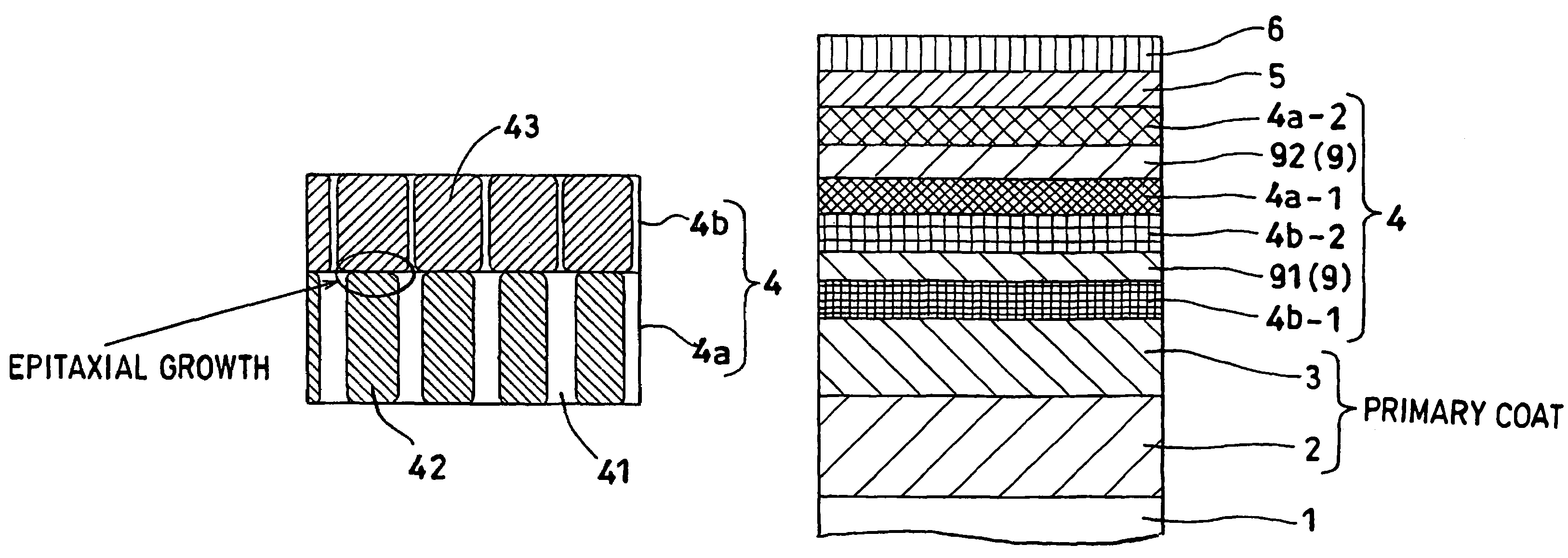
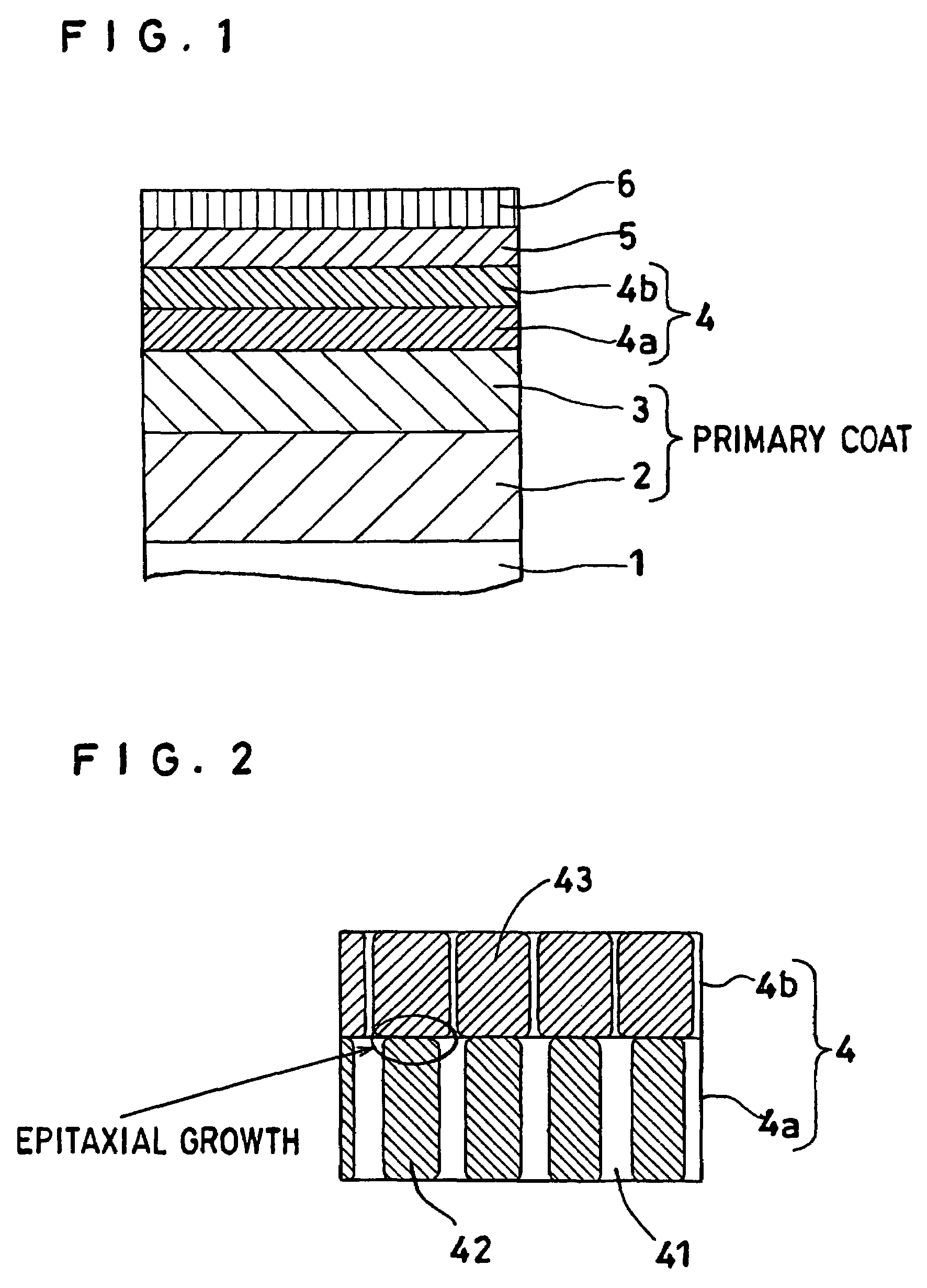
A magnetic recording medium which is provided on a nonmagnetic substrate 1 with at least an orientation-controlling layer 3 for controlling the orientation of a layer formed directly thereon, a perpendicularly magnetic layer 4 having an easily magnetizing axis oriented mainly perpendicularly relative to the nonmagnetic substrate 1, and a protective layer 5 and characterized in that the perpendicularly magnetic layer 4 includes two or more magnetic layers, that at least one of the magnetic layers is a layer 4a having Co as a main component and containing Pt as well and containing an oxide and that at least another of the magnetic layers is a layer 4b having Co as a main component and containing Cr as well and containing no oxide.

Description

CROSS REFERENCE TO RELATED APPLICATIONS[0001]This application is an application filed under 35 U.S.C. § 111(a) claiming the benefit pursuant to 35 U.S.C. §119(e)(1) of the filing date of Provisional Application No. 60 / 462,298 filed Apr. 14, 2003 pursuant to 35 U.S.C. §111(b).TECHNICAL FIELD[0002]This invention relates to a magnetic recording medium which is provided on a nonmagnetic substrate with at least an orientation-controlling layer for controlling the orientation of a layer formed directly thereon, a perpendicularly magnetic layer having an easily magnetizing axis oriented mainly perpendicularly relative to the nonmagnetic substrate, and a protective layer, to a method for the production thereof and to a magnetic recording and reproducing apparatus.BACKGROUND ART[0003]The hard disk drive (HDD) that is one kind of the magnetic recording and reproducing apparatus has the recording density thereof growing at present at an annual rate of 60% or more. The trend of this growth is s...

Claims


Application Information

Patent Timeline
Patent Type & Authority Patents(United States)
IPC IPC(8): G11B5/66C23C16/40G11B5/673G11B5/64
CPCG11B5/65G11B5/656G11B5/66G11B5/672
Inventor SAKAWAKI, AKIRASHIMIZU, KENJIKOBAYASHI, KAZUOSAKAI, HIROSHIOIKAWA, SOICHIIWASAKI, TAKESHIMAEDA, TOMOYUKINAKAMURA, FUTOSHI
Owner SHOWA DENKO KK
Learn More