Ultrasound transducer and method of producing the same

a transducer and ultrasonic technology, applied in the field of ultrasonic transducers, can solve the problems of requiring a comparatively high manufacturing expenditure, and achieve the effect of improving manufacturing capabilities and suitable mounting arrangements

Inactive Publication Date: 2008-12-30
KERNFORSCHUNGSZENTRUM KARLSRUHE GMBH
View PDF12 Cites 55 Cited by
  • Summary
  • Abstract
  • Description
  • Claims
  • Application Information

AI Technical Summary

Benefits of technology

[0016]Preferably, the conductor structure extends only below areas of the piezoelectric body which are acoustically inactive or only comparatively slightly active, for example, to the immediate edge areas of the piezoelectric body or the areas in which the piezo electric body is not utilized for the generation or the reception of an ultrasound impulse. “Slightly active”in this connection means that, although in these areas, the ultrasound measuring characteristics of the ultrasound transducer are measurable, it does not detrimentally affect or influence the ultrasound examination. Preferably, the piezoelectric body is not controlled in those areas by the sender or receiver electronics so that these areas can be excluded from the area covered by the upper electrode. The total area of these sections corresponds maximally to 10% of the coverage of the piezoelectric body. Preferably, for avoiding ripple effects, the conductor structures are so formed that a statistically determined support for the lower electrode of the piezoelectric body is provided for example, by way of three support points. Small support points cause, upon pressing the piezoelectric body onto the support, a high area pressure level, that is, tension peaks but advantageously also provide for a high contacting reliability of the electrode by way of the support points.
[0019]As wafers, commercially available wafers for microwave or high frequency applications may be used which consist of a homogeneous plastic-ceramic compound materials (that is, without fiber inclusions) and which fulfill not only the material requirements for a coupling layer as mentioned above, but which are available advantageously as industrial products of homogeneous and constant material quality and which are reproduceable with the exact geometries and are reasonably priced. The wafers have the important advantage that they are commercially available in various thicknesses and have the required mechanical and chemical properties.
[0022]As piezoelectric bodies monolithic unstructured bodies are suitable and also transducers which comprise a multitude of individual transducer elements so as to form a converter array. Particularly in connection with the last mentioned structure, the invention provides for much improved manufacturing capabilities since a first unstructured piezo-electric body is connected to the wafer and is then structured. Using a suitable method such as sawing or ultrasound cutting, the body can be cut into the individual converter elements. The wafer advantageously provides for a suitable mounting arrangement for the manufacturing steps and stabilizes during the segmenting the individual transducer elements on the wafer.

Problems solved by technology

This is followed generally by an adaptation of the coupling layer thickness to the frequency (wavelength) of the transducer element by means of mechanical and therefore expensive follow-up working or fine-cutting of the coupling layer.
Furthermore, the connections to the two electrodes are established by individual wire connections which requires a comparatively high manufacturing expenditures.

Method used


Image

  • Ultrasound transducer and method of producing the same
  • Ultrasound transducer and method of producing the same
  • Ultrasound transducer and method of producing the same

Examples


Embodiment Construction

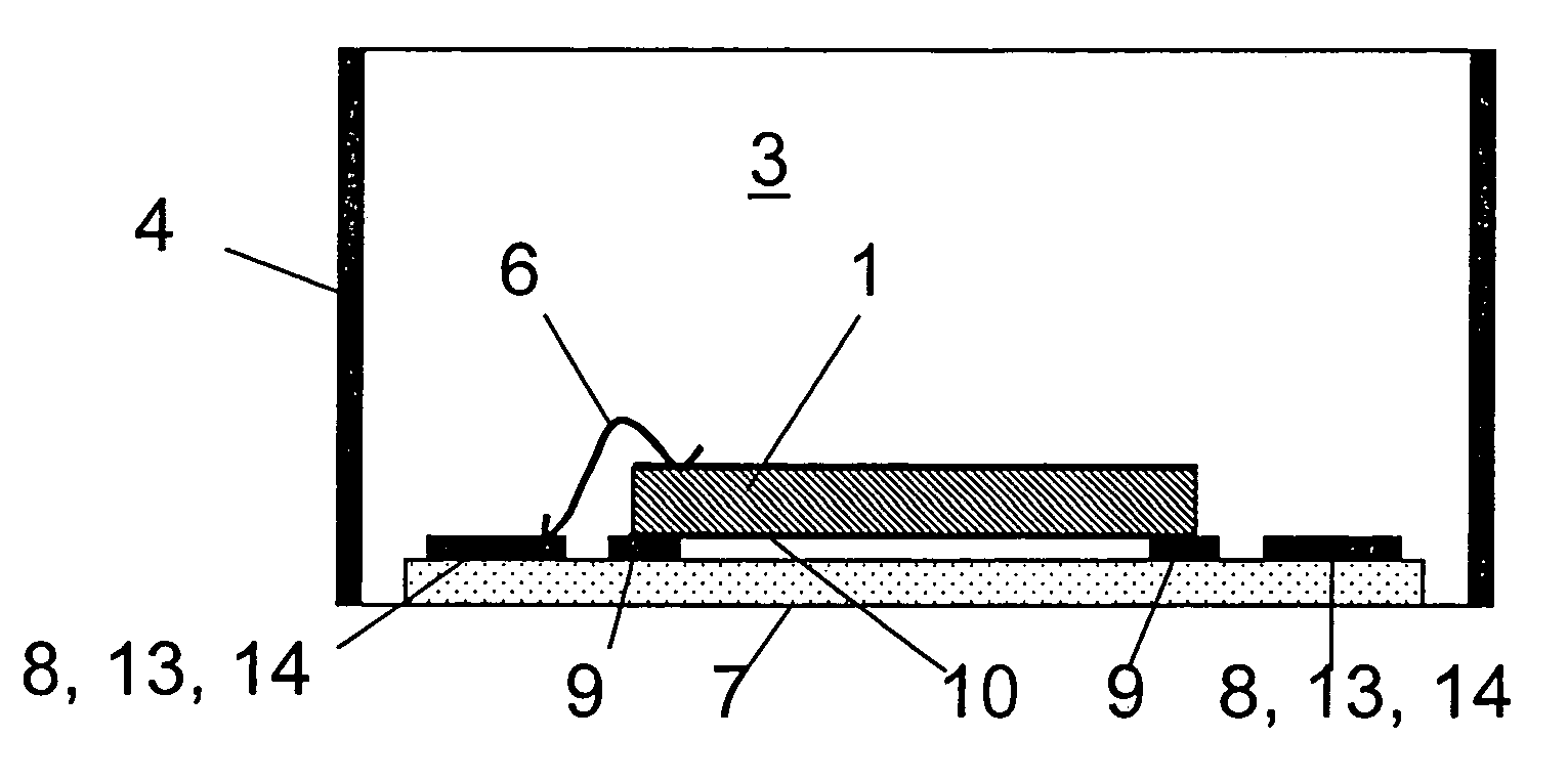
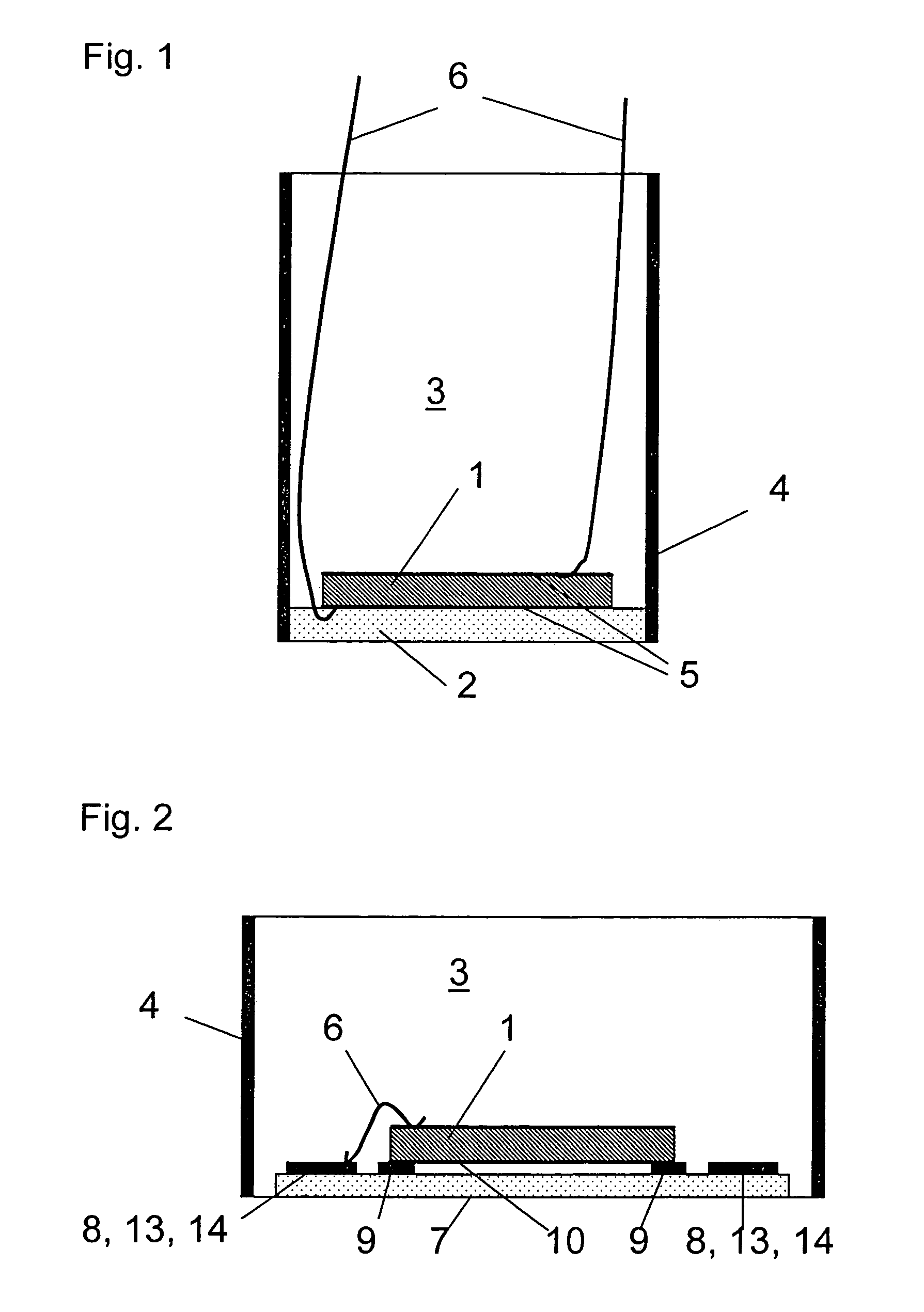
[0033]FIG. 1 shows the basic components of an ultrasound transducer of conventional design which includes a piezoelectric body, the transducer 1, which is firmly connected to the coupling layer 2. The coupling layer 2 has a thickness which is ideally ¼ of the wavelength λ and forms the end wall of a housing 4. Within the housing 4, an attenuation body 3 is disposed which, in the present case, is in the form of a casting material. The two electrodes 5 of the transducer 1 are connected to a control and measuring unit, which is not shown, via electrical cable connectors 6. As mentioned initially, the thickness of the coupling layer is obtained by an expensive mechanical finishing operation.

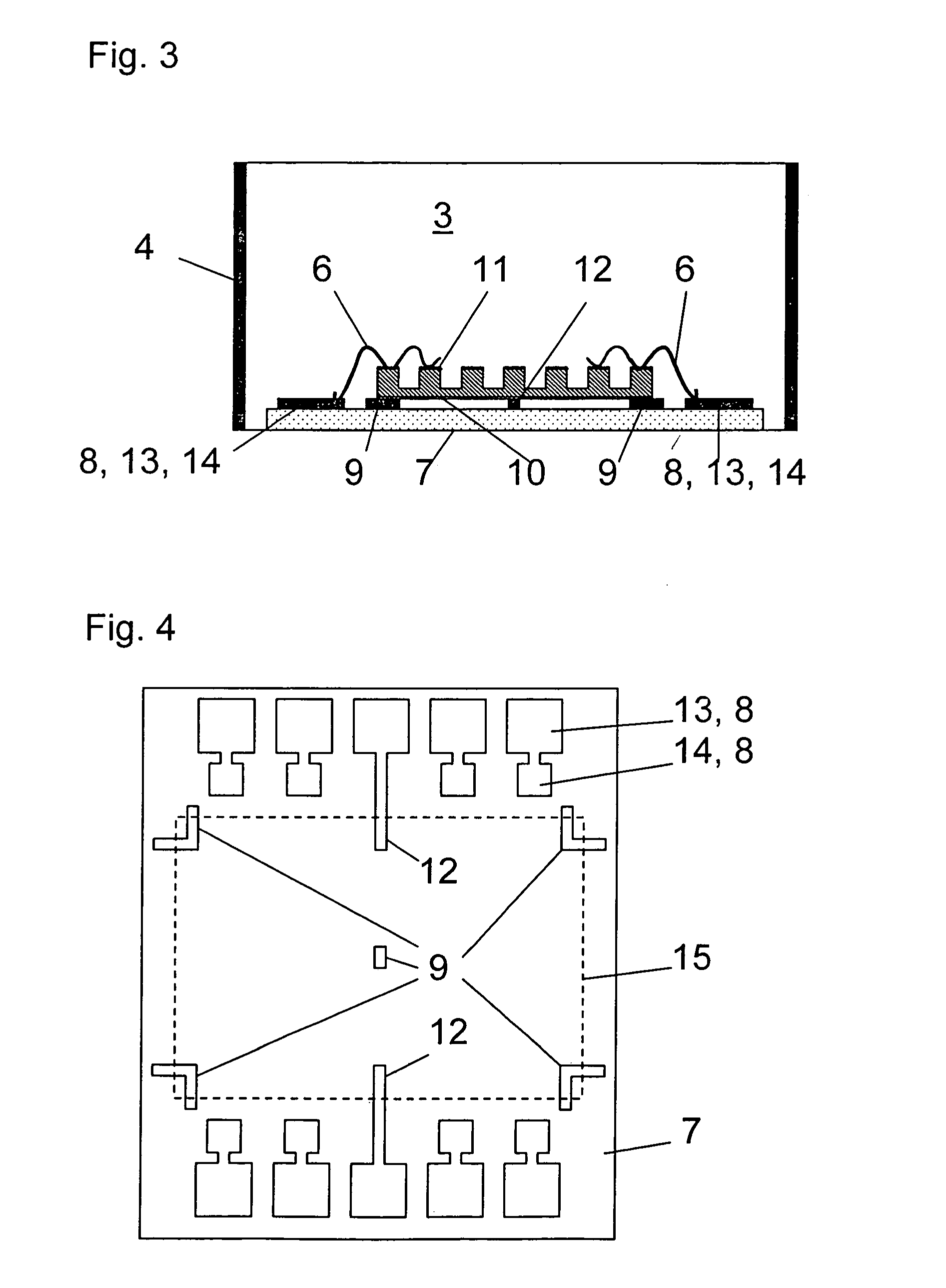
[0034]In order to avoid these problems, an HF plate of the type referred to earlier is used as an adaptation layer and holder for the further working. Onto this plate then a piezoelectric transducer is cemented. The wafer used in connection with the exemplary embodiment is suitable for ultrasound tra...


PUM

PropertyMeasurementUnit
frequencyaaaaaaaaaa
sizeaaaaaaaaaa
sizeaaaaaaaaaa

Abstract

In an ultrasound transducer arrangement comprising at least one piezoelectric body with a lower and an upper electrode and a coupling layer including a wafer on which the ultrasound transducers are disposed and are connected to the lower electrode, a conductor structure of uniform height is disposed on the wafer and is in contact with the lower electrode and any space between the piezoelectric body and the wafer is completely filled with a cement material.

Description

[0001]This is a Continuation-In-Part Application of International Application PCT / EP2005 / 004389 filed Apr. 23, 2005 and claiming the priority of German Application 10 2004022838.8 filed May 8, 2004.BACKGROUND OF THE INVENTION[0002]The present invention relates to an ultrasound transducer, comprising at least one piezoelectric body with at least one lower and one upper electrode and a coupling layer with on a wafer surface on which the ultrasound transducer is disposed and connected to the lower electrode and to a method of manufacturing such an ultrasound transducer.[0003]Like in many areas of electronic devices and sensors, the components for the apparatus and the systems continue to become smaller and more powerful also for ultrasound systems. An important part of such systems are ultrasound sensors, which, in most cases, are designed specifically for a particular measuring problem. Costs and quality of components are both very important in the development of ultrasound systems. I...

Claims


Application Information

Patent Timeline
Patent Type & Authority Patents(United States)
IPC IPC(8): H01L41/08B06B1/06H01L41/047
CPCB06B1/0607B06B1/0644Y10T29/49005Y10T29/4908A61B8/4494H01L2224/48472H01L2224/48137
Inventor SCHLOTE-HOLUBEK, KLAUSGOBEL, GEORGSTOTZKA, RAINER
Owner KERNFORSCHUNGSZENTRUM KARLSRUHE GMBH
Why Eureka
Try Eureka