Surface mount type temperature-compensated crystal oscillator

a temperature-compensated crystal and oscillator technology, applied in the direction of oscillator, pulse generator, pulse technique, etc., can solve the problems of affecting the operation of the oscillator, the oscillator cannot meet predetermined standards sufficiently, and the frequency stability will worsen at startup, so as to increase the frequency stability, suppress any temperature rise, and increase the thermal dissipation effect

Inactive Publication Date: 2008-12-30
NIHON DEMPA KOGYO CO LTD
View PDF3 Cites 26 Cited by
  • Summary
  • Abstract
  • Description
  • Claims
  • Application Information

AI Technical Summary

Benefits of technology

[0021]The present invention ensures that the active element and the temperature sensor are disposed internally at a distance at diagonally opposite corner regions of the IC chip at which the IC terminals are positioned. In this case, as shown by the above-described observation, the IC terminals are positioned at diagonally opposite corner portions of the IC chip and the temperature drops. In other words, heat generated at one diagonally opposite corner portion at which the active element that acts as a heat source is disposed dissipates thermally through the IC terminals, bumps, and circuit terminals in that one diagonally opposite corner portion.
[0022]Since the other diagonally opposite corner region at which the temperature sensor is disposed is at the greatest distance from the heat source in the first diagonally opposite corner region, and also heat is dissipated out through the IC terminals, bumps, and circuit terminals, any temperature rise due to the heat source has little effect thereon and thus any temperature rise due to thermal dissipation is suppressed. The temperature detected by the temperature sensor is therefore little affected by the effects of a temperature rise due to the heat source, so that the operating temperature of the crystal oscillator is close to the ambient temperature.
[0023]This configuration ensures that the temperature sensor can detect a temperature that is close to the operating temperature of the crystal oscillator (ambient temperature), even if there is a temperature rise due to the heat source at the startup of the temperature-compensated oscillator, and can supply a compensation voltage corresponding to that operating temperature to the variable-voltage capacitor element. The frequency stability can therefore be increased at the startup of the temperature-compensated oscillator.
[0024]Since present invention also provides IC terminals for thermal dissipation that are affixed by ultrasonic thermal crimping using bumps to a central region of the IC chip, the thermal dissipation effect can be further increased together with the IC terminals provided along the two sides of the IC chip. Similarly, it is thus possible to suppress any temperature rise due to the heat source and obtain an detected temperature that is close to the operating temperature (ambient temperature) of the crystal oscillator, together with the corresponding compensation voltage. This increases the frequency stability of the temperature-compensated oscillator at startup.
[0025]In addition, the present invention ensures that the IC terminals that are provided at diagonally opposite corner portions of the IC chip are connected electrically to the mounting terminals provided on the outer base surface of the main container. Since this means that the mounting terminals such as the power source, ground, and output terminals are connected to the circuit pattern on the set substrate, the thermal dissipation effect is increased.
[0026]Furthermore, since the present invention ensures that the active element of the oscillating circuit that acts as a heat source and the temperature sensor of the temperature-compensated device are integrated into and disposed at diagonally opposite corner regions of the IC chip, there is synergy with the above-described effect so that the temperature detected by the temperature sensor comes even closer to the operating temperature of the crystal oscillator.

Problems solved by technology

However, there is a problem with a temperature-compensated oscillator of the above-described configuration, in that the degree of stability is lost at start-up and thus the oscillator cannot satisfy predetermined standards sufficiently.
Since the oscillation frequency f varies from the nominal frequency fo, the frequency stability will worsen at startup.
Erroneous temperature-compensation operation caused by the temperature difference between the IC chip 102 and the crystal oscillator 103 at startup can therefore be a big problem.
In this case, there is a large thermal dissipation effect from the IC terminals connected to the mounting terminals, particularly the power source, ground, and output terminals.

Method used


Image

  • Surface mount type temperature-compensated crystal oscillator
  • Surface mount type temperature-compensated crystal oscillator
  • Surface mount type temperature-compensated crystal oscillator

Examples


first embodiment

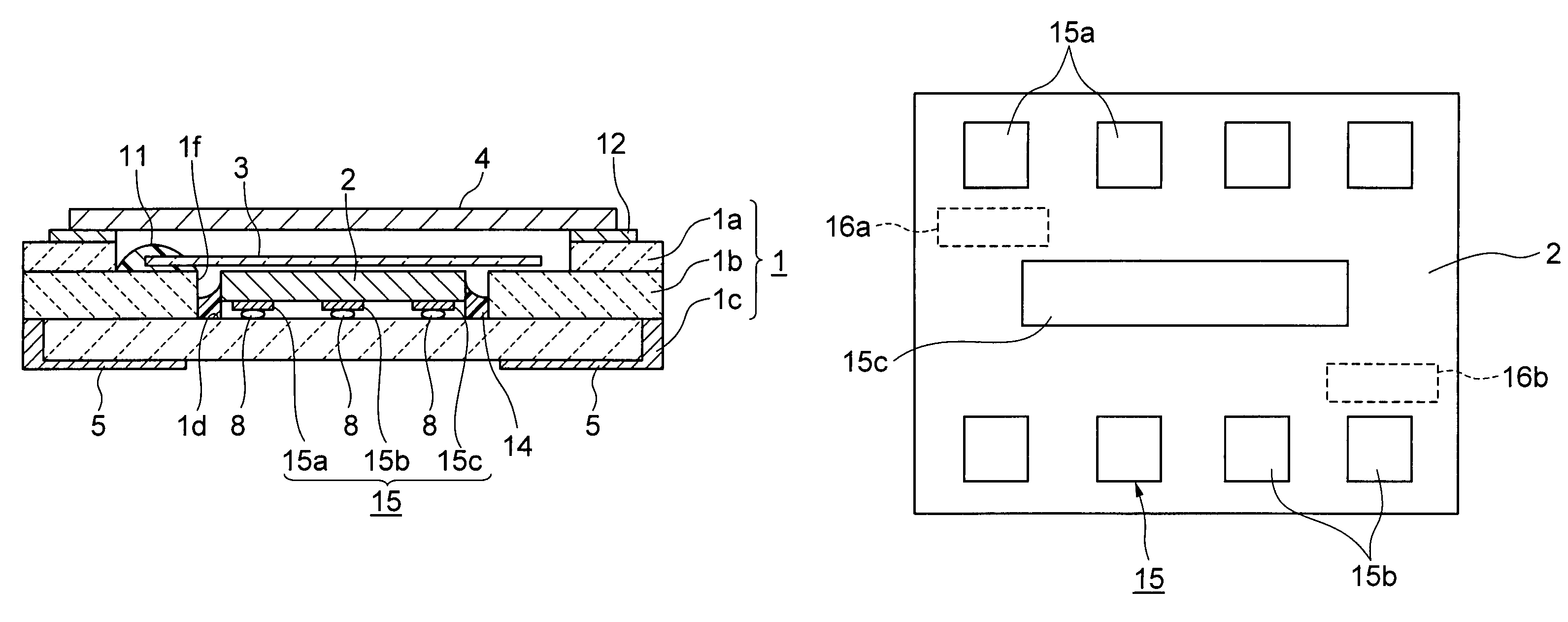
[0035]FIG. 1A shows a first embodiment of a temperature-compensated oscillator for surface mounting in accordance with the present invention, where FIG. 1A is a sectional view thereof and FIG. 1B is an enlarged plan view thereof as seen from below the IC chip used therein.

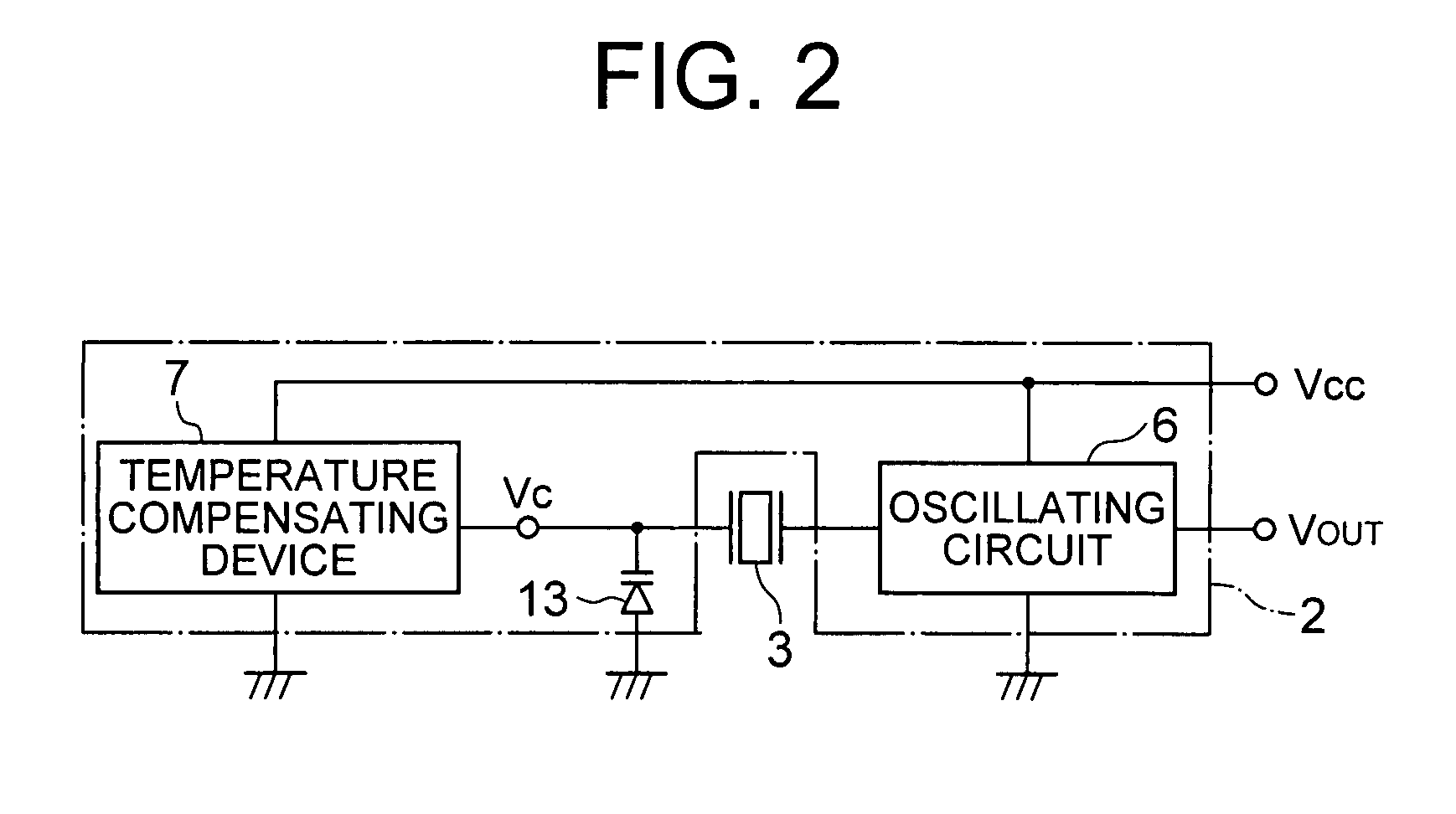
[0036]In the temperature-compensated oscillator of the present invention, a circuit function surface of an IC chip 2 in which are integrated an oscillating circuit 6 and a temperature-compensating device 7 (shown in FIG. 2) is affixed to an inner base surface 1d of a main container 1 formed from stacked ceramic layers 1a, 1b, and 1c, by ultrasonic thermal crimping or reflow using bumps 8, as shown in FIG. 1A. IC terminals 15 (15a and 15b) are disposed at diagonally opposite corner portions of one main surface of the IC chip 2, which is the circuit function surface thereof, as shown in FIG. 1B. Both sides of one edge portion of a crystal piece 3 (see FIG. 3B) extending from output electrodes (reference number 110 in...

second embodiment

[0042]FIG. 3 shows a second embodiment of the temperature-compensated oscillator of the present invention, where FIG. 3A is a sectional view thereof and FIG. 3B is a plan view from above with the metal cover and crystal piece removed.

[0043]In addition to the configuration of the first embodying example described above, a thermally conductive adhesive 14 is applied to the outer periphery of the side surfaces (outer edges) of the IC chip 2, as shown in FIGS. 3A and 3B. This ensures that the outer periphery of the side surfaces (outer edges) of the IC chip 2 are affixed to the inner base surface 1d of the main container 1. In this case, the thermally conductive adhesive 14 is packed into the space between the outer periphery of the IC chip 2 and the inner walls of the main container 1. The thermally conductive adhesive 14 is formed of a thermally conductive material mixed into a base adhesive substance, where the thermally conductive material is formed of an insulating substance such a...

third embodiment

[0048]FIG. 5 shows a third embodiment of the present invention, where FIG. 5A is a sectional view thereof and FIG. 5B is a plan view from above with the metal cover and crystal piece removed.

[0049]In this third embodiment, upper and lower stages 1e and 1g are formed circumferentially in the inner wall step portion of the main container 1, as shown in FIG. 5A. In addition, both sides of one end portion of the crystal piece 3 are affixed to the upper stage 1e. A metal film 14a is formed on the lower stage 1g of a metal with a high thermal conductivity, such as Au or Cu. The metal film 14a is connected electrically to a ground terminal among the mounting terminals 5, by means such as a via hole (not shown in the figure). The outer periphery of a metal plate 15 is affixed to the lower stage 1g and a central region thereof is affixed to cover the remaining main surface of the IC chip 2, by the electrically conductive adhesive 11 that is a thermally conductive material.

[0050]This configur...


PUM


Abstract

A temperature-compensated crystal oscillator for surface mounting wherein an IC chip into which is integrated a temperature-compensated device having an oscillating circuit and a temperature sensor, which supplies a compensation voltage to a variable-voltage capacitor element of the oscillating circuit, and which also has IC terminals disposed along two edges comprising at least diagonally opposite corner portions of one main surface that acts as a circuit function surface is affixed with the use of bumps to an inner base surface of a main container that is concave in section, and one edge portion of a crystal piece is affixed to an inner wall step portion of the main container; wherein an active element of the oscillating circuit that acts as a heat source and a temperature sensor of the temperature-compensated device are disposed at diagonally opposite corner regions of the IC chip at the greatest distance apart. In addition, IC terminals for thermal dissipation are provided in a central region of the IC chip. The present invention provides a temperature-compensated oscillator for surface mounting in which the temperature-compensation operation at startup is satisfactory and frequency stability is maintained.

Description

BACKGROUND OF THE INVENTION[0001]1. Field of the Invention[0002]The present invention relates to a temperature-compensated crystal oscillator for surface mounting (hereinafter called a “temperature-compensated oscillator”) and, in particular, to a surface-mount type oscillator that provides temperature compensation reliably at the startup thereof.[0003]Since temperature-compensated oscillators for surface mounting are compact, lightweight, and have a high degree of frequency stability with respect to temperature changes, they are used as built-in frequency sources in portable devices such as mobile phones, particularly in changing temperature environments. One type is a temperature-compensated oscillator in which a temperature-compensating device and an oscillating circuit are integrated into an IC chip which is hermetically sealed in together with a crystal piece.[0004]2. Description of Related Art[0005]A temperature-compensated oscillator of the prior art is shown illustratively i...

Claims


Application Information

Patent Timeline
Patent Type & Authority Patents(United States)
IPC IPC(8): H03B1/00
CPCH03L1/023H03L1/04
Inventor ISHIKAWA, TAKAAKIKUBO, KUICHIASAMURA, FUMIOONO, KOZO
Owner NIHON DEMPA KOGYO CO LTD
Why Eureka
Try Eureka