
Microwave transmission unit including lightning protection

a transmission unit and microwave technology, applied in waveguide devices, emergency protection arrangements for limiting excess voltage/current, installation of lighting conductors, etc., can solve problems such as lightning strokes, damage to metal coating heating, and damage to metallisation layer heating

Active Publication Date: 2008-12-30
INTEL CORP
View PDF8 Cites 19 Cited by
  • Summary
  • Abstract
  • Description
  • Claims
  • Application Information

AI Technical Summary

Benefits of technology

[0011]The object is according to the invention obtained by the metal coating of the cabinet being 5-200 μm thick and the microwave transmission unit including a lightning conductor which is dimensioned so as to conduct lightning current without being damaged to any serious extent, and which is electrically connected to the outer conductor of the first coaxial connector and to the outer conductor of the second coaxial connector, said lightning conductor includes a metal body of a cross-sectional area of at least 10-200 mm2. As a result, a lightning current running in an outer conductor of a coaxial connector connected to the first coaxial connector can be efficiently conducted to the outer conductor of a coaxial connector connected to the second coaxial connector or vice versa without causing damaging heatings of the relatively thin metal layer of the cabinet.
[0017]According to a preferred embodiment of the microwave transmission unit according to the invention, the lightning conductor may be electrically connected to the outer conductor of the first coaxial connector and to the outer conductor of the second coaxial connector by means of fittings which are screwed into the lightning conductor and flanges on the coaxial connectors by means of screws. The resulting embodiment is particularly simple.
[0018]According to an embodiment of the microwave transmission unit according to the invention, the first coaxial connector and the second coaxial connector may be arranged at the same end of the cabinet and fastened to a common plate-shaped metal fitting forming the lightning conductor. The resulting embodiment is particularly simple.
[0023]According to yet another embodiment of the microwave transmission unit according to the invention, the microwave filter may include a trimming plate of solid metal with threaded holes for trimming screws, where the ends of said trimming screws together with the resonators define capacitances, and where the trimming plate forms the lightning conductor. The resulting embodiment is particularly simple.

Problems solved by technology

Strokes of lightning are particularly problematic because it must be possible to divert or conduct very strong lightning currents away from vulnerable components.
However, a strong lightning current can cause a damaging heating of the metal coating due to the relatively highohmic resistance and low heat capacity of said metal coating.
It is not mentioned in this patent how the metallisation layer can be protected from a strong lightening current running between the outer conductors of the coaxial connectors and causing a damaging heating of the metallisation layer.

Method used


Image

  • Microwave transmission unit including lightning protection
  • Microwave transmission unit including lightning protection
  • Microwave transmission unit including lightning protection

Examples


second embodiment

[0026]FIG. 3 is a sectional view of a microwave filter according to the invention, and

[0027]FIG. 4 is an extended, sectional, perspective view of the microwave filter of FIG. 3.

BEST MODES FOR CARRYING OUT THE INVENTION

first embodiment

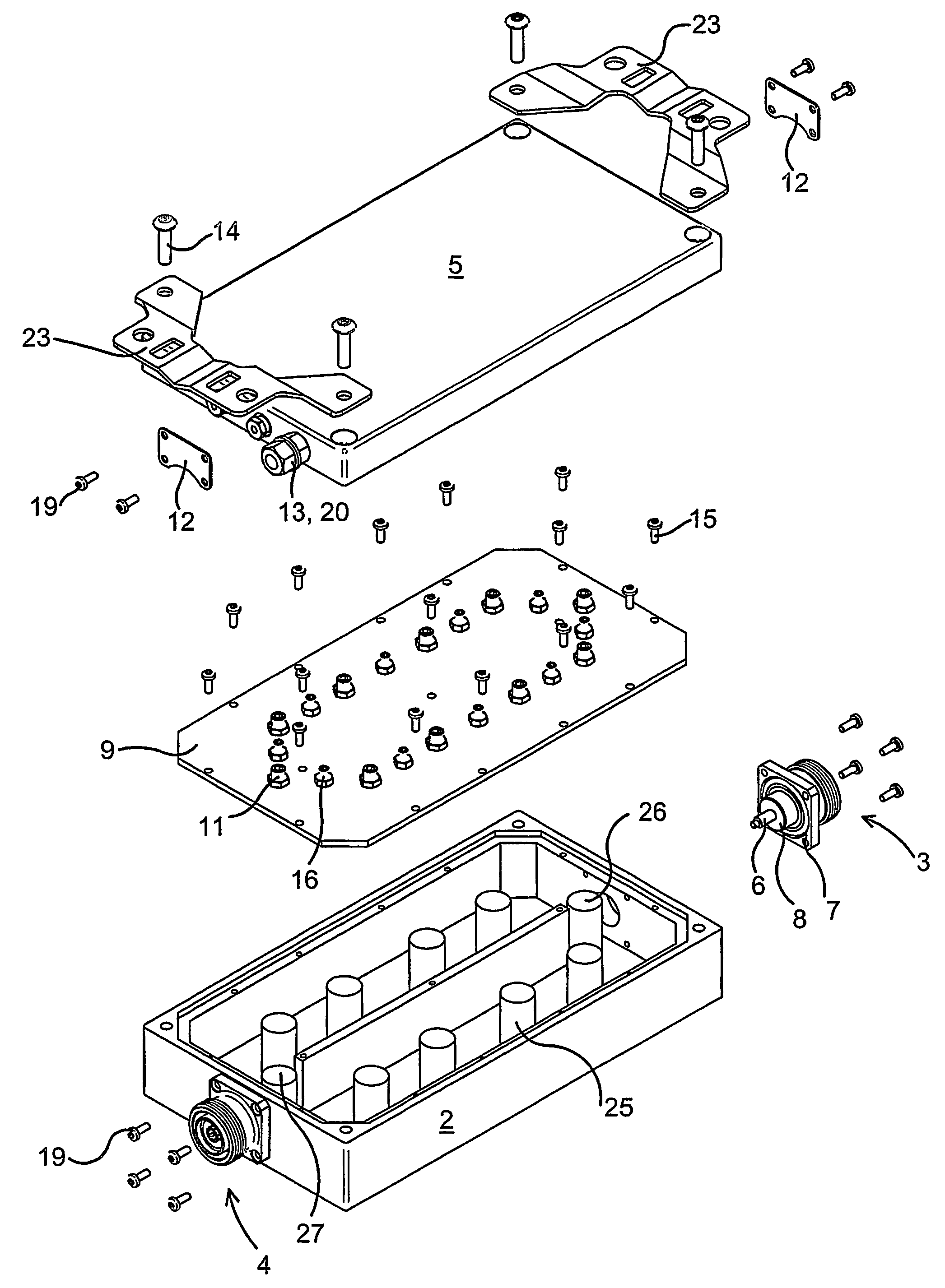
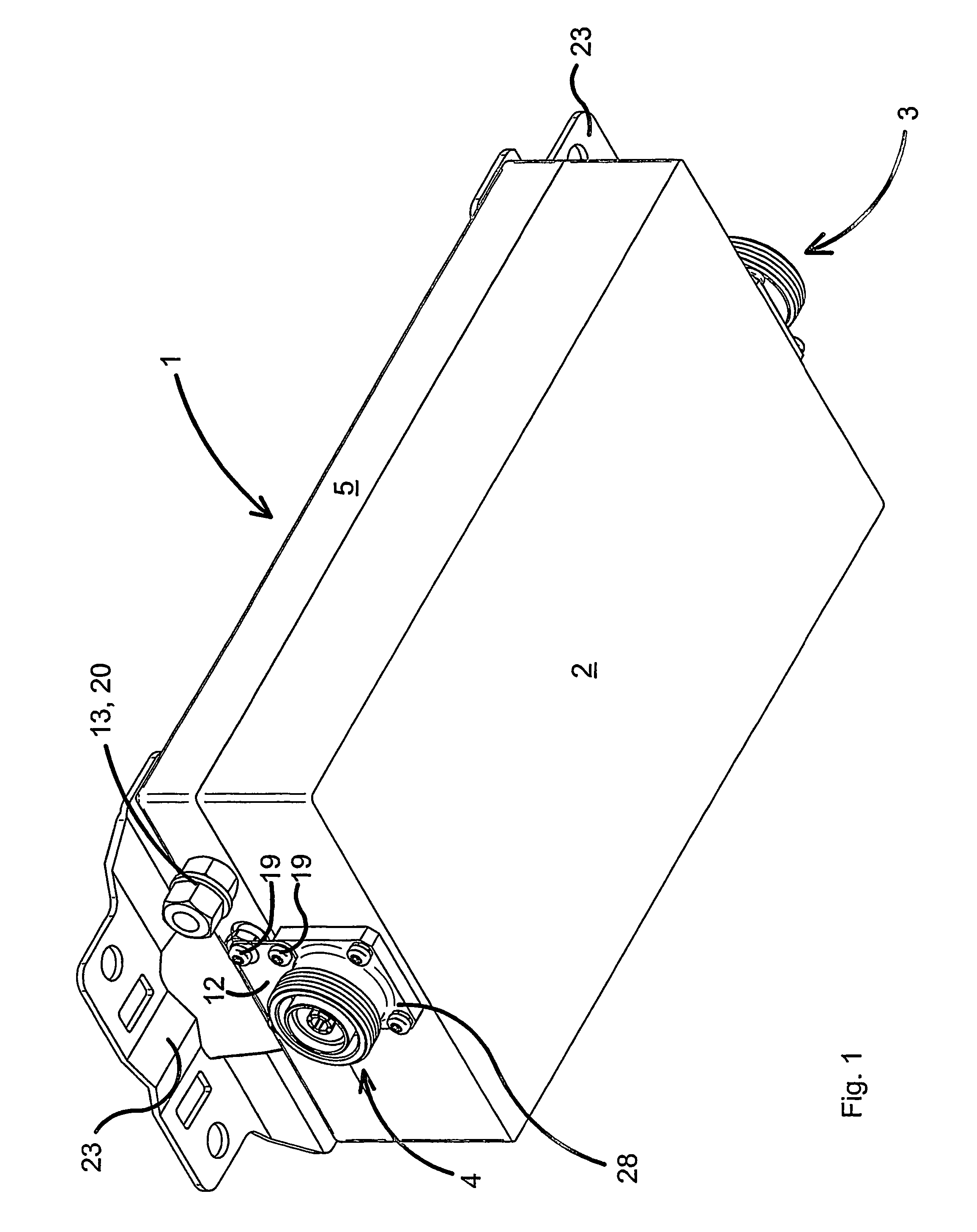
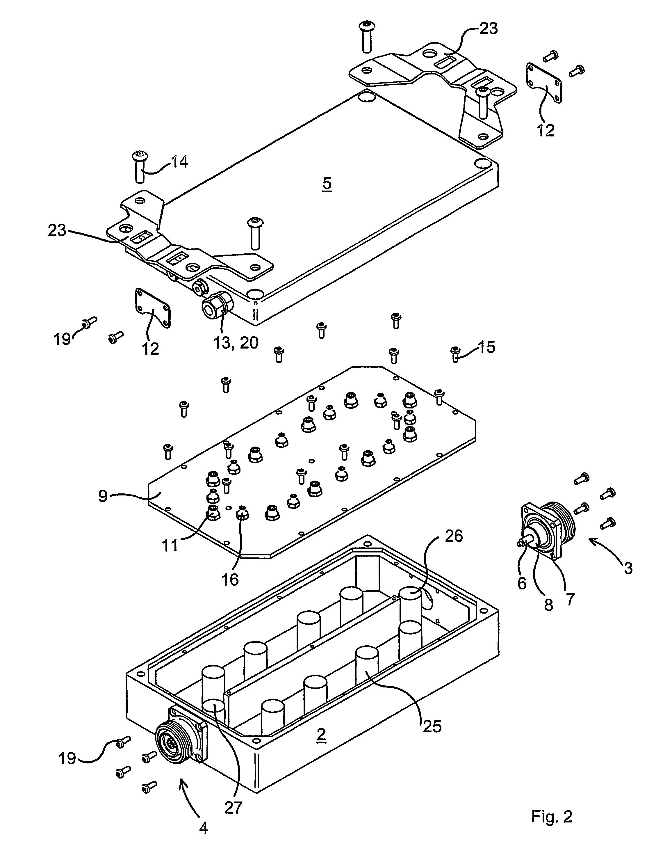
[0028]FIG. 1 illustrates microwave filter 1 according to the invention. The microwave filter 1 includes a cabinet 2, a cover 5, an almost invisible input coaxial connector 3 and an output coaxial connector 4. Here the cover 5 is made of solid metal and forms per se a lightning conductor. A fitting 12 of metal plate is screwed by means of screws 19 into both the cover 5 and a flange 28 on the output coaxial connector 4, said flange continuing directly into the outer conductor of the output coaxial connector 4. Correspondingly, the input coaxial connector 3 is connected to the cover 5 by means of a fitting 12 at the invisible end. An earth screw13 with nuts 20 screwed thereon is mounted in the cover 5 and can be used for connecting said cover to an aerial mast or the like by means of a cable. A mounting member 23 is screwed into the cover 5 and used for mounting the microwave filter on an aerial mast or the like.

[0029]FIG. 2 is an extended perspective view of the microwave filter of F...


PUM


Abstract

Microwave transmission unit, especially a microwave filter (1), and including a cabinet (2) with a first coaxial connector (3) and a second coaxial connector (4), where both coaxial connectors include an inner conductor (6) and an outer conductor (7), said cabinet (2) being made of a non-conducting material, such as plastics, and coated with a metal layer. The microwave transmission unit (1) includes a lightning conductor (5) which is dimensioned so as to conduct lightning current without being damaged to any serious extent, and which is electrically connected to the outer conductor (7) of the first coaxial connector (3) and to the outer conductor (7) of the second coaxial connector (4).

Description

TECHNICAL FIELD[0001]The invention relates to a microwave transmission unit, especially a microwave filter, and including a cabinet with a first coaxial connector and a second coaxial connector, where both coaxial connectors include an inner conductor and an outer conductor, said cabinet being made of a non-conducting material, such as plastics, and coated with a metal layer.BACKGROUND ART[0002]Microwave filters are often in form of so-called cavity resonators where the resonances in a hollow cabinet are utilized for filtering specific frequencies. The cavity of the cabinet can be shaped in many ways. An input coaxial conductor conducts alternating currents with differing frequencies to a cabinet. Columnar resonators are provided in the cabinet, said resonators being of a length typically corresponding to one fourth of the wavelength of the frequency at which the filter is to operate.[0003]The inner conductor of the input coaxial connector is connected to an input resonator, and the...

Claims


Application Information

Patent Timeline
Patent Type & Authority Patents(United States)
IPC IPC(8): H01P7/02H01P1/205H01P1/30H01Q1/12H01Q1/22H01Q1/50H02G13/00
CPCH01P1/2053H01P1/30H01Q1/12H01Q1/50H02G13/00
Inventor HOLST, THORSTENHAGENSEN, MORTENJENSEN, CARSTEN GADEGAARDJENSEN, STIG
Owner INTEL CORP
Learn More