
Shock protection for disk drive embedded in an enclosure

Active Publication Date: 2008-12-30
MAXTOR
View PDF32 Cites 79 Cited by
  • Summary
  • Abstract
  • Description
  • Claims
  • Application Information

AI Technical Summary

Benefits of technology

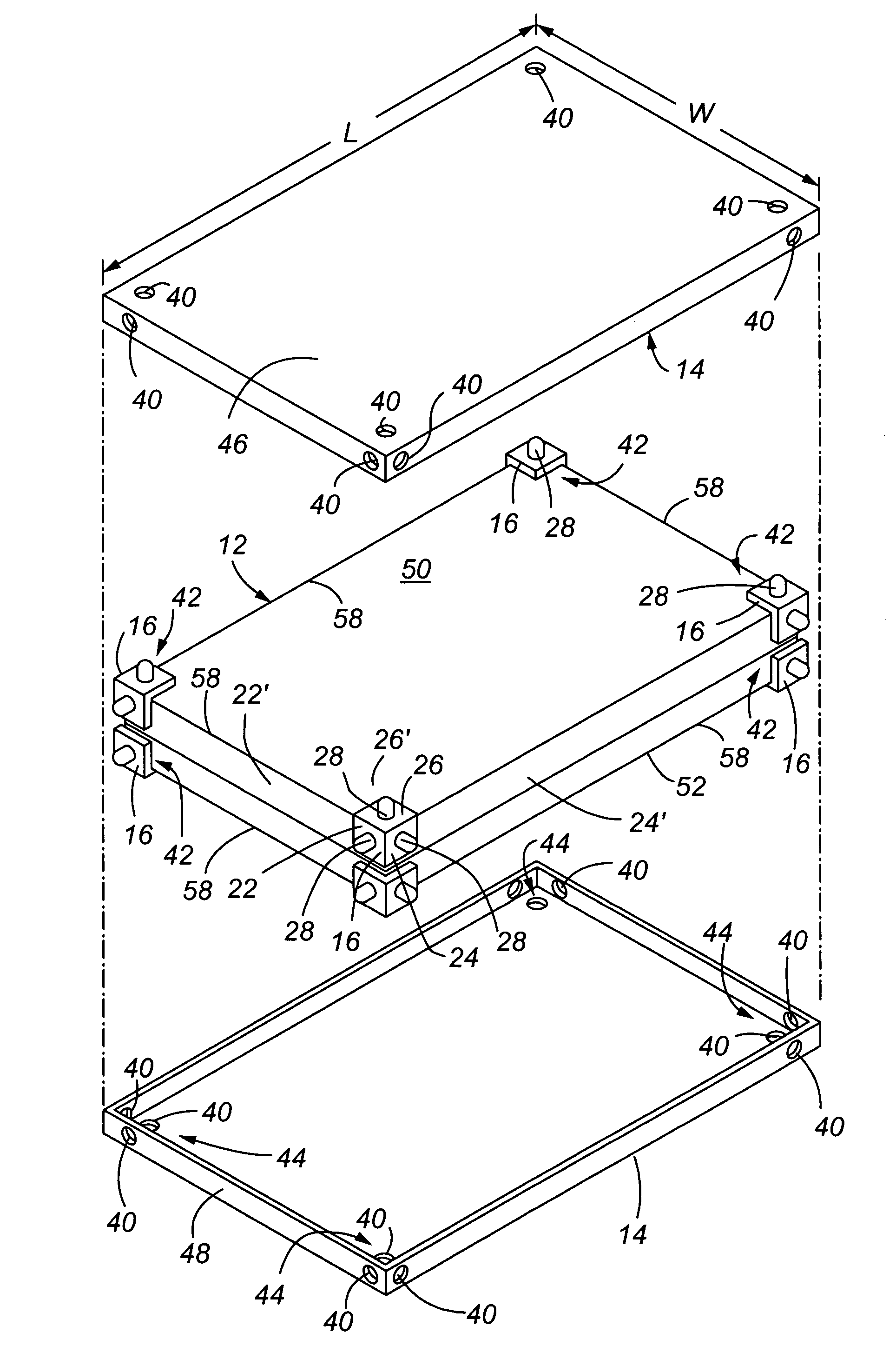
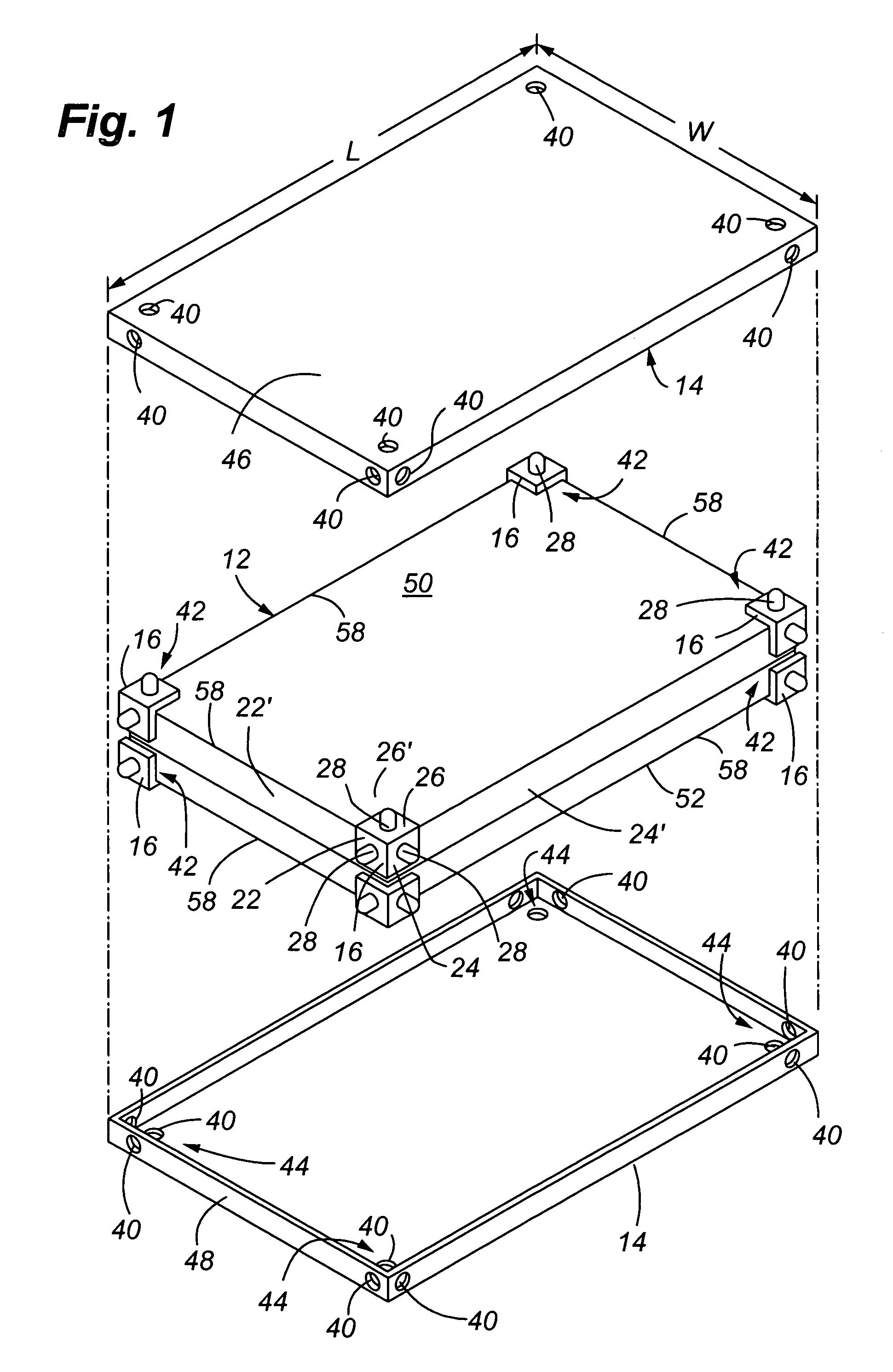
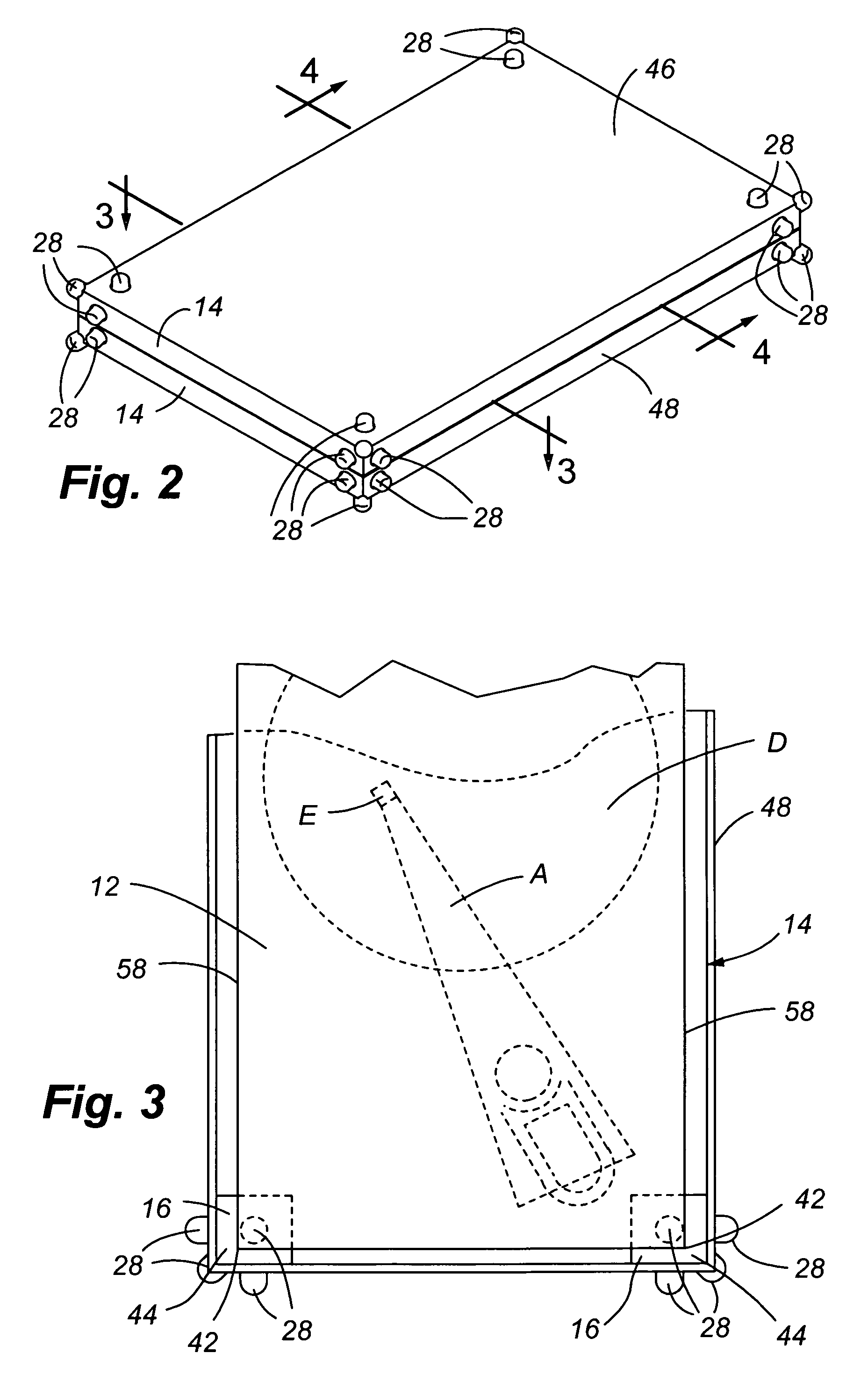
[0011]It is one aspect of the present invention to provide a shock absorbing system for use with a disk drive that is contained in an external enclosure, which enclosure is then incorporated into a portable end product, such as a laptop computer, PDA, consumer electronic device or the like. Moreover, it is an aspect of the present invention to provide the shock absorbing system without increasing the physical size of the enclosure and, preferably, reducing the physical dimensions of the enclosure, thereby facilitating reducing the size of the portable end product. More specifically, one embodiment of the present invention includes one or more shock absorbing devices that are positioned between the external corners of the disk drive housing and the internal corners of the external enclosure containing the disk drive housing and, perhaps, other components. The shock absorbers include a plurality of protuberances that extend from mutually orthogonal portions of the shock absorbers. To increase the shock absorbing characteristics of the shock absorbers, the protuberances extend through openings in the enclosure. The additional compression height gained by extending the protuberances through the enclosure provides additional damping and significantly lowers the amplitude of an input shock pulse for a given overall height of the absorber, including the enclosure thickness. Further, the protuberance increases the duration of a drop onto a hard surface by transferring deformation energy into the body portions of the shock absorber, thereby causing the body portions to deform and substantially dissipating the shock energy. It should be appreciated that the shock absorbers are not limited to a position at the corners of the disk drive housing or enclosure. The shock absorbers may be positioned along edges or on surfaces.
[0012]The protuberances are also adapted to deform in many directions to help protect the disk drive in any orientation. More specifically, since the protuberances emanate from the enclosure, they are more apt to receive the initial impact which may be felt in an axial or lateral direction, i.e., glancing blows. Thus, since the protuberances help dissipate the shock in their own right, the body portions of the shock absorbers may be made thinner overall.
[0014]It is yet another aspect of the present invention to provide a shock absorber that is easy to construct. Protuberances may be molded or machined into the body portions of the shock absorbers. In addition, the cavity may be formed in the shock absorber after molding or directly molded into the shock absorber. The cavities allow the absorber to more fully or completely fit on intended surfaces by accommodating variations in surfaces and edges. The materials utilized for the shock absorber of the present invention are generally known in the art. One embodiment of the present invention utilizes rubber, however, any resiliently deflectable material capable of elastic deformation may be utilized without departing from the scope of the invention. Further, although a generally hemispherical protuberance is shown herein, one skilled in the art will appreciate that columnar, prismatic, pyramid or any other shape of protuberance may be utilized without departing from the scope of the invention. The present invention also does not require any new assembly steps to be implemented and adhesives are not necessarily required. The shock absorbers are capable of a friction fit.
[0015]Still yet another aspect of the present invention is to provide a shock absorber that is compatible with many types of enclosures. A standard enclosure with upper and lower halves may be used wherein the halves are retrofitted somewhat so that apertures are provided for the receipt of the protuberances. Also, enclosures with sides, top or bottom openings may be employed in some electronic devices, which are easily used in conjunction with shock absorbers of the present invention.

Problems solved by technology

Further, the protuberance increases the duration of a drop onto a hard surface by transferring deformation energy into the body portions of the shock absorber, thereby causing the body portions to deform and substantially dissipating the shock energy.

Method used


Image

  • Shock protection for disk drive embedded in an enclosure
  • Shock protection for disk drive embedded in an enclosure
  • Shock protection for disk drive embedded in an enclosure

Examples


Embodiment Construction

[0030]Referring to FIGS. 5A, B and C, three representative prior art disk drive housings 12 are shown which, in turn, are positioned in an outer envelope or enclosure 14. A space 18 is formed between the disk drive housing 12 and the enclosure 14, allowing room for other components, such as circuit boards, batteries, liquid crystal displays (LCDs), associated with the operation of the disk drive, as well as providing space for deflection of the enclosure. An actual hard disk drive is mounted within the housing 12, as is represented in FIG. 4. Disk drives generally are comprised of one or more rotating disks D and an associated actuator assembly A with at least one read / write element E for the storage and the access of data.

[0031]Disk drives are susceptible to physical shocks, particularly high amplitude, short duration shocks associated with dropping the disk drive onto a hard surface. As shown in FIGS. 5A and 5C, a plurality of shock absorbers 16 are positioned between the housing ...


PUM


Abstract

A shock absorbing device for protecting a hard disk drive housing found primarily in portable electronic devices. The shock absorbers include protuberances that emanate from the body of the shock absorber and that extend through apertures provided in the enclosure. Thus, the physical shock is taken up by the body of the shock absorber as well as the protuberances, which increase the compression height of the shock absorber and increase the shock damping characteristics of the shock absorber. This permits decreasing the size of the enclosure, which is often desirable to consumers.

Description

CROSS REFERENCE TO RELATED APPLICATIONS[0001]This application claims the benefit of U.S. Provisional Patent Application Ser. No. 60 / 617,257 filed Oct. 8, 2004, which is incorporated by reference herein in its entirety.FIELD OF THE INVENTION[0002]The present invention relates to a shock absorbing device that protects a magnetic hard disk drive against the effects of physical shocks. More particularly, the available compression height of the shock absorber is increased to reduce the effects of high impact events while maintaining or decreasing the overall size of the enclosure surrounding the disk drive.BACKGROUND OF THE INVENTION[0003]Electronic devices such as laptops, personal data assistants (PDAs), MP3 players, CD players, etc., are very popular. However, these mobile devices often utilize delicate and expensive components, such as magnetic disk drives, that are prone to damage when dropped. Because of the small size and portability of these devices, they are prone to be dropped,...

Claims


Application Information

Patent Timeline
IPC IPC(8): H05K5/00A47B81/00H05K7/00
CPCG11B25/043G11B33/08
Inventor OLIVER, DANIEL B.
Owner MAXTOR
Learn More