Encryption method, cryptogram decoding method, encryptor, cryptogram decoder, and communication system

a cryptogram decoding and encryption technology, applied in the field of encryption methods, can solve the problems of not being able to discriminate coherent light, not being able to know which one of the set of coherent light beams is coherent, and the quantum cipher technique is considered impossible to decode (unconditionally safe) against any attack method, etc., to achieve the effect of greater encryption strength

Active Publication Date: 2008-12-30
FUJITSU LTD +1
View PDF11 Cites 16 Cited by
  • Summary
  • Abstract
  • Description
  • Claims
  • Application Information

AI Technical Summary

Benefits of technology

[0124]According to the present invention described above, the discrete DSR technique using a physical random number is performed and a discrete signal output of two bits can be obtained, therefore, it is made possible to perform desired channel coding and because of this, it is possible to provide an encryption / cryptogram decoding technique having a far greater encryption strength than the conventional mathematical encryption (the same encryption strength as that of the above-mentioned classic Y-00 scheme cryptography) and capable of being stored as data in electric memories and a variety of recording media that can be used in electromagnetic wave communication and electrical communication and further of minimizing the influence on the communication rate without being influenced by noises.

Problems solved by technology

In such a situation, recently, a quantum cipher technique is considered as impossible to decode (unconditionally safe) against any attack method including the above-mentioned known plain text attack.
However, an interceptor does not know the pseudo random number that the legitimate transmitter and receiver use, therefore, it is not possible for him / her to know which one of sets of coherent light beams is used in communication.
Because of this, in order to decode the intercepted cryptogram, it is necessary for the interceptor to correctly know the phase of the coherent light beam the transmitter has sent to demodulate the light signal having been subjected to multilevel phase modulation, however, it is not possible for the interceptor to discriminate the coherent light beam indicative of the state of plain text (“1” or “0”) from the coherent light beam the phase angle of which is close to that of the coherent light beam in question for demodulation even if the interceptor has intercepted the coherent light beam flowing through the transmission channel because it is buried in the quantum fluctuation.
On the other hand, the above-mentioned scheme cannot be used with electric signals or electromagnetic waves because it uses a quantum-mechanical communication medium.
It is necessary to use a communication medium having quantum-mechanical properties in order to perform the above-mentioned Y-00 scheme in a quantum system, therefore, its application range is limited.
In such a situation, the applicants of the present invention have proposed a classic Y-00 scheme for performing the Y-00 scheme using pseudo random numbers and physical noises in the classic physical system (for example, Japanese Patent Application No. 2004-260512 etc.) However, the embodiments of the classic Y-00 scheme so far apply analog DSR, therefore, its output is necessarily a multilevel signal and application of the encryption technique is not possible to a recording media such as an electric memory, a flexible disc, a CD (Compact Disc), and a DVD (Digital Versatile Disc), etc.

Method used


Image

  • Encryption method, cryptogram decoding method, encryptor, cryptogram decoder, and communication system
  • Encryption method, cryptogram decoding method, encryptor, cryptogram decoder, and communication system
  • Encryption method, cryptogram decoding method, encryptor, cryptogram decoder, and communication system

Examples


first embodiment

[1] Configuration of the Encryptor in the First Embodiment

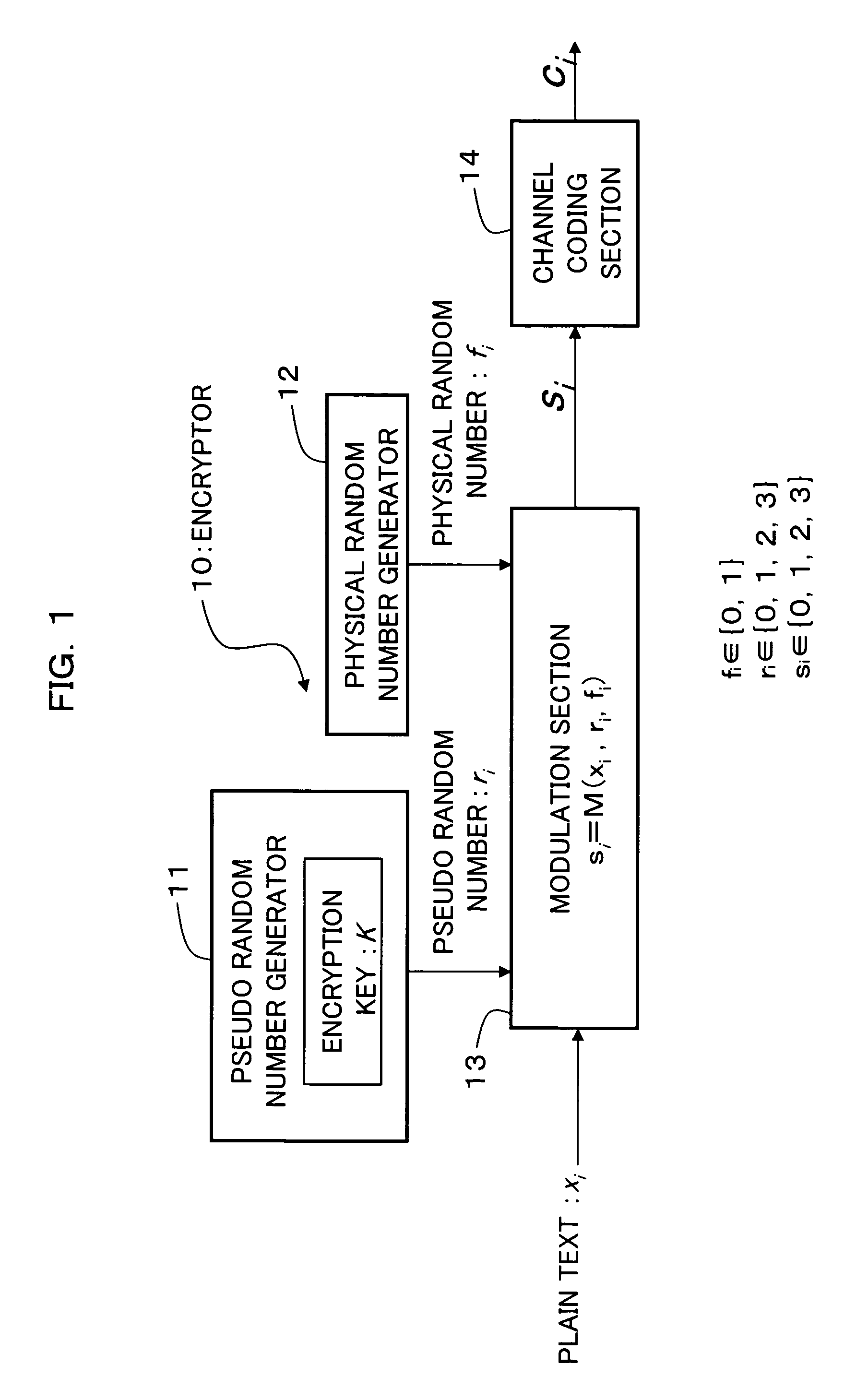
[0162]FIG. 1 is a block diagram showing a configuration of an encryptor as a first embodiment of the present invention and as shown in FIG. 1, an encryptor 10 in the first embodiment is configured so as to provide a pseudo random number generator 11, a physical random number generator 12, a modulation section 13, and a channel coding section 14.

[0163]The pseudo random number generator (first pseudo random number generation section, modulation pseudo random number generation section) 11 generates and outputs a modulation pseudo random number (first pseudo random number) ri based on an encryption key K set in advance. For example, if the encryption key K is a 100-bit binary number, a (2100−1)-bit binary number, that is, a pseudo random number with a period of (2100−1) bits is generated from the physical random number generator 11. The output from the physical random number generator 11 is dealt with as a pseudo random number ri...

second embodiment

[8] Encryption / Cryptogram Decoding Technique in the Second Embodiment

[0491]In the encryption / cryptogram decoding technique in the first embodiment described above, the modulation section 13 performs modulation using, for example, the modulation three-variable function si=M (xi, ri, fi) as shown in FIG. 7(A) for all of the bits of the plain text xi to be transmitted and modulates each bit of the plain text xi to be transmitted into the two-bit output si. Therefore, the number of bits of the modulation output si is double the number of bits of the plain text xi to be transmitted.

[0492]The encryption / cryptogram decoding technique as the second embodiment of the present invention to be explained below with reference to FIG. 11 to FIG. 16 is a combination of the encryption / cryptogram decoding technique described above as the first embodiment with reference to FIG. 1 to FIG. 10 and the stream cipher scheme described above as the prior art with reference to FIG. 18, and in the second embod...

fifth embodiment

[11] Encryption / Cryptogram Decoding Technique in the Fifth Embodiment

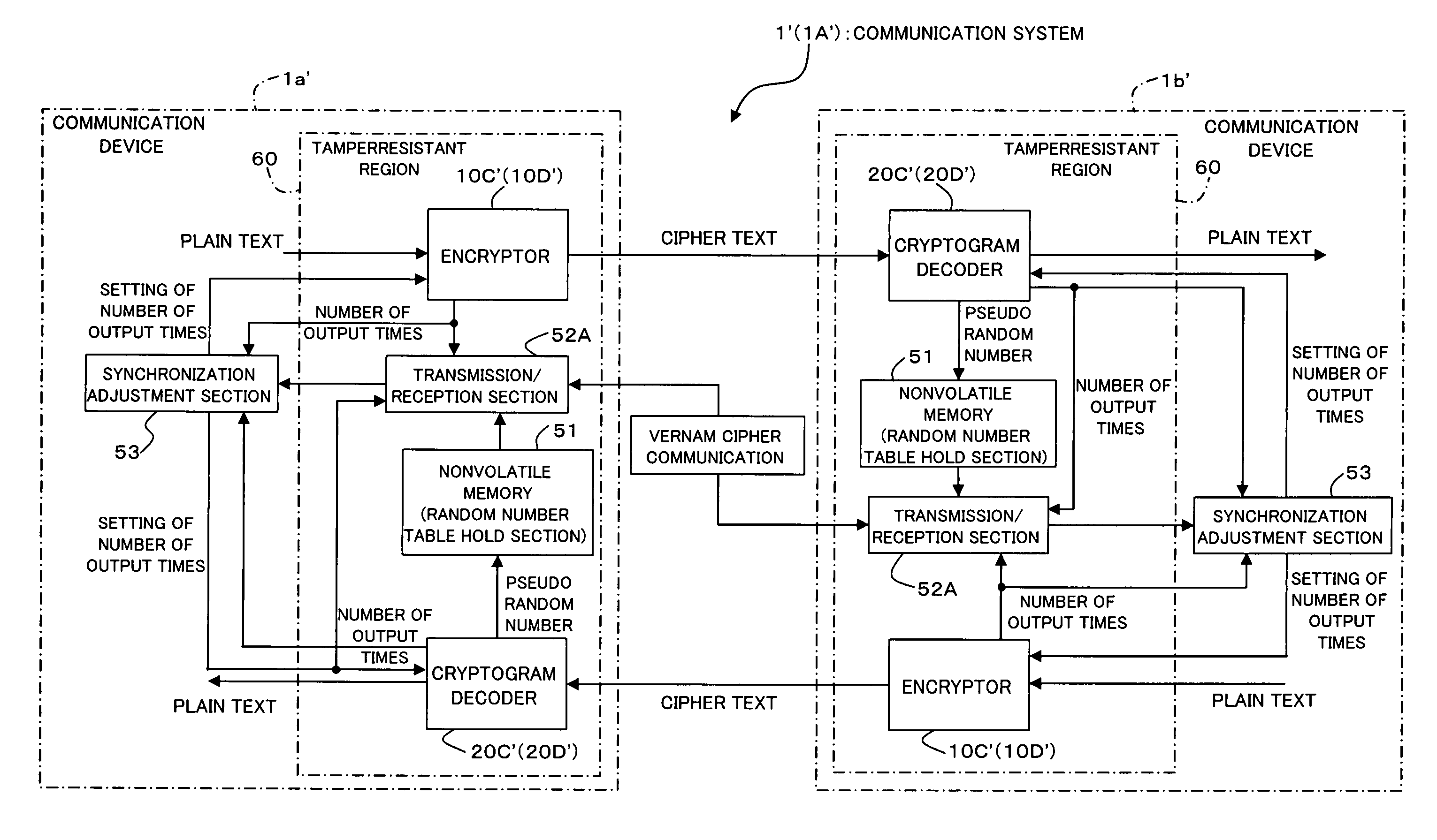
[0647]FIG. 27 is a block diagram showing the entire configuration of the communication systems 1′ and 1A′ to which the encryption / cryptogram decoding technique as the fifth and sixth embodiments of the present invention has been applied and the communication system 1 in the third embodiment shown in FIG. 27 is configured so as to provide two communication devices 1a′ and 1b′ connected so that communication is possible to each other via a communication network etc. For the communication system 1′ in the fifth embodiment and the communication system 1A′ in the sixth embodiment to be described later, a case will be explained where the two communication devices 1a′ and 1b′ are connected so that communication is possible to each other via a communication channel (signal line) in which tampering may occur and the two communication devices 1a′ and 1b′ perform synchronization processing by Vernam cipher communication being...


PUM


Abstract

An encryption technique having a greater encryption strength than conventional mathematical encryption by using classic physical random numbers etc., including a step for modulating one-bit input data into a coded signal by associating it with a discrete value of at least two bits determined by pseudo random numbers and physical random numbers and a step for channel-coding and outputting the coded signal, wherein 1) the coded signal can be demodulated into the input data by the pseudo random number, 2) the number of sets of input data, pseudo random number, and physical random number corresponding to a particular discrete value is equal for two values of the input data, and 3) the number of sets of pseudo random number and physical random number corresponding to respective values of the input data and respective values of the discrete value is equally associated also with any set of them.

Description

BACKGROUND OF THE INVENTION[0001](1) Field of the Invention[0002]The present invention relates to an encryption / cryptogram decoding technique used in a system in which information is encrypted before being transmitted and received and, more particularly, to an encryption / cryptogram decoding technique having a far greater encryption strength than conventional mathematical encryption by using the classic physical random number etc. instead of quantum fluctuation in the Yuen quantum cryptography scheme and capable of being applied to a variety of media.[0003](2) Description of the Related Art[0004]In a network at present, as an encryption method, mathematical encryption such as shared key encryption is used. Typical examples include stream cipher (classic encryption). FIG. 18 is a block diagram showing a configuration of a general transmission / reception system to which the stream cipher has been applied, and a transmission / reception system 100 shown in FIG. 18 is configured so as to pr...

Claims


Application Information

Patent Timeline
Patent Type & Authority Patents(United States)
IPC IPC(8): H04L9/28H04K1/00
CPCH04L9/0852H04L9/0662H04L9/0891H04L2209/08
Inventor YOSHIDA, SETSUOHIROTA, OSAMUONAKA, HIROSHI
Owner FUJITSU LTD
Why Eureka
Try Eureka