Thermal sensing

a technology of sensing and temperature, applied in the field of thermodynamic sensing, can solve the problems of a number of limitations of the previous techniques for sensing or detecting heat or temperatur

Inactive Publication Date: 2009-01-06
PALO ALTO RES CENT INC
View PDF54 Cites 39 Cited by
  • Summary
  • Abstract
  • Description
  • Claims
  • Application Information

AI Technical Summary

Problems solved by technology

Previous techniques in sensing or detecting heat or temperature have a number of limitations.

Method used


Image

  • Thermal sensing
  • Thermal sensing
  • Thermal sensing

Examples


Embodiment Construction

[0029]The below-described implementations can be applied in measuring thermal effects of chemical reactions as well as in various other ways, some of which are described in the parent application, incorporated herein by reference. In describing some implementations, the terms “target molecule”, “ligand”, “test ligand”, “target protein”, and other terms are used herein with substantially the same meanings as set forth in the parent application.

[0030]As used herein, the term “thermal change” encompasses the release of energy in the form of heat or the absorption of energy in the form of heat.

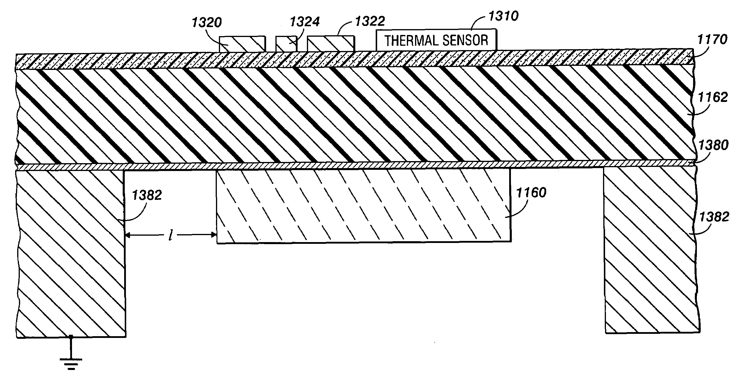
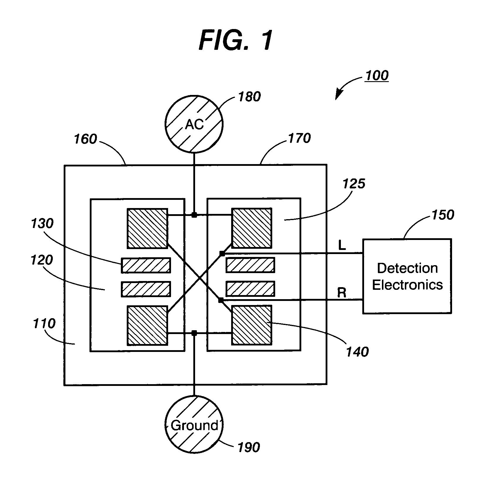
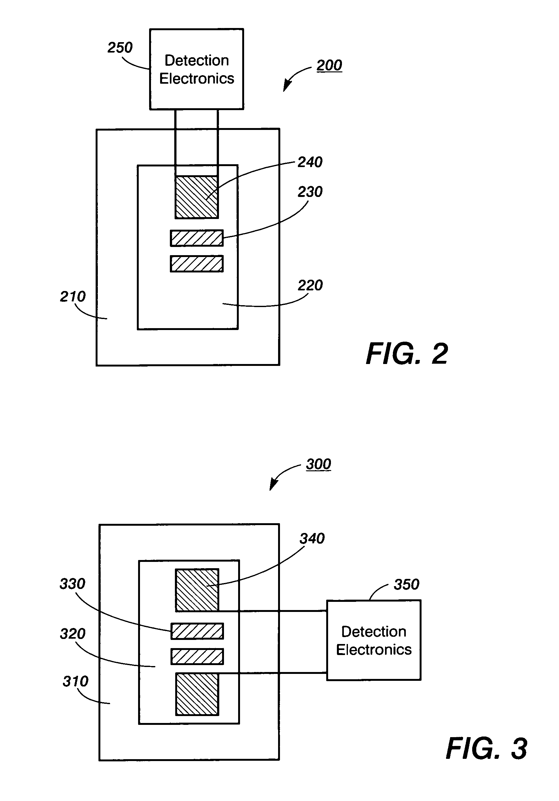
[0031]As used herein, a “nanocalorimeter” is a calorimeter capable of measuring in the range of nanocalories. Exemplary implementations of the present invention can be applied generally in calorimeters and calorimeter arrays. More specifically, implementations can be applied in nanocalorimeters and nanocalorimeter arrays that enable measurement of enthalpic changes, such as enthalpic changes arisi...


PUM

PropertyMeasurementUnit
thicknessaaaaaaaaaa
thicknessaaaaaaaaaa
thicknessaaaaaaaaaa

Abstract

In thermal sensing devices, such as for calorimetry, a support layer or central layer can have a thermometer element or other thermal sensor on one side and a thermally conductive structure or component on the other. The thermally conductive structure can conduct temperature or other thermal input signals laterally across the support layer or central layer. The temperature or signals can then be provided to the thermometer element, such as by thermal contact through the support layer. An electrically conducting, thermally isolating anti-coupling layer, such as of gold or chromium, can reduce capacitive coupling between the thermally conductive structure and the thermometer element or other thermal sensor.

Description

RELATED APPLICATIONS[0001]This application is a continuation-in-part of U.S. patent application Ser. No. 10 / 114,611, filed Apr. 1, 2002 (U.S. Patent Application Publication No. 2003 / 0186453, now issued as U.S. Pat. No. 7,141,210) (“the parent application”), which is incorporated herein by reference in its entirety. Other continuations-in-part of the parent application include U.S. patent application Ser. No. 10 / 303,446, filed Nov. 22, 2002 (U.S. Patent Application Publication No. 2003 / 0186454) and Ser. No. 10 / 303,500, filed Nov. 22, 2002 (U.S. Patent Application Publication No. 2003 / 0186455), both of which are incorporated herein by reference in their entireties.[0002]This invention was made with government support under contract HHSN266200400058C / NO1-AI-40058 awarded by the National Institutes of Health. The government has certain rights in the invention.BACKGROUND OF THE INVENTION[0003]The present invention relates generally to techniques that sense thermal stimuli. In particular,...

Claims


Application Information

Patent Timeline
Patent Type & Authority Patents(United States)
IPC IPC(8): G01K17/00G01F1/68G01K1/00G01K7/30G01N25/20G01N25/48G01N27/00
CPCG01K7/30G01K17/00G01K17/006G01N25/482
Inventor BRUCE, RICHARD H.DE BRUYKER, DIRKTORRES, FRANCISCO E.WOLKIN, MICHAL V.
Owner PALO ALTO RES CENT INC
Why Eureka
Try Eureka