Variably adjustable bi-directional derotation bracing system

a bracing system and bi-directional technology, applied in the field of orthopaedic support devices, can solve the problems of affecting the stability of the rotational stability the movement downward on the leg, and the loss of rotational stability that might be provided by the device, and the current mechanical hinged bracing system has not yet demonstrated biomechanical efficacy in preventing injuries

Inactive Publication Date: 2009-01-06
MATHEWSON PAUL R
View PDF60 Cites 37 Cited by
  • Summary
  • Abstract
  • Description
  • Claims
  • Application Information

AI Technical Summary

Benefits of technology

[0031]The present invention is directed to providing a new form of orthopedic brace which more effectively controls or delimits axial rotation in a physiological joint. Unlike prior examples of orthopedic braces, the present device is a flexible arrangement of bracing members which actively resist axial rotation in the joint by providing a flexible, circumferentially spiraling bracing device. A further consequence of this restrictive action is that translation in the joint is also delimited. The present invention effectively eliminates the rigid structural elements, as well as the mechanical hinge structures of previous orthopedic bracing systems, rendering it easy to use, comfortable to wear and suitable for use during normal everyday activity, including sporting activities. A further advantage of the present invention is the compressive force provided by the unique arrangement of circumferentially spiraling bracing members which provides proprioception to the wearer in increasing his awareness of the relationship of the target joint to the rest of his body thus enabling the wearer to recognize proper rotation and placement of the joint.
is the compressive force provided by the unique arrangement of circumferentially spiraling bracing members which provides proprioception to the wearer in increasing his awareness of the relationship of the target joint to the rest of his body thus enabling the wearer to recognize proper rotation and placement of the joint.

Problems solved by technology

Even so, the weight of such devices results in the device migrating downwardly on the leg and any rotational stability that might be provided by such devices is lost.
Current mechanical hinged braces have, as yet, not demonstrated biomechanical efficacy in helping to prevent injuries resulting from such rotational forces.
Such devices do not, and are not specifically meant to, limit the movement of a joint under stress and, therefore, are not able to fulfill the role of an orthopedic brace.
These devices are not designed to limit joint rotation.
Indeed, elastic fabric bandages are not effective at preventing joint rotation under physiologically significant loads because of their elasticity in all dimensions.
Thus, they cannot accomplish the objectives for which a true bracing system is designed.
Known bracing systems are not specifically designed to effectively constrain axial rotation about a human or animal joint.

Method used


Image

  • Variably adjustable bi-directional derotation bracing system
  • Variably adjustable bi-directional derotation bracing system
  • Variably adjustable bi-directional derotation bracing system

Examples


Embodiment Construction

[0047]The principal elements of the orthopedic brace of the present invention are described fully in co-pending application Ser. No. 09 / 004,010, the contents of which are incorporated herein by reference. The following disclosure describes additional embodiments of the principal orthopedic brace invention and employs the same reference numerals used in Ser. No. 09 / 004,010.

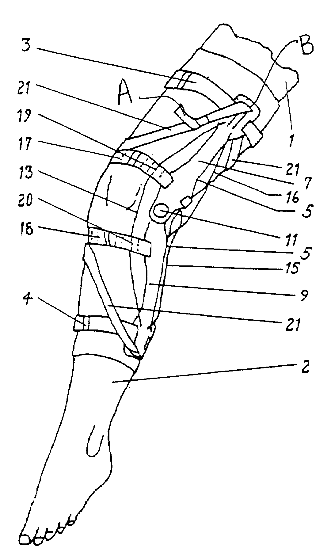
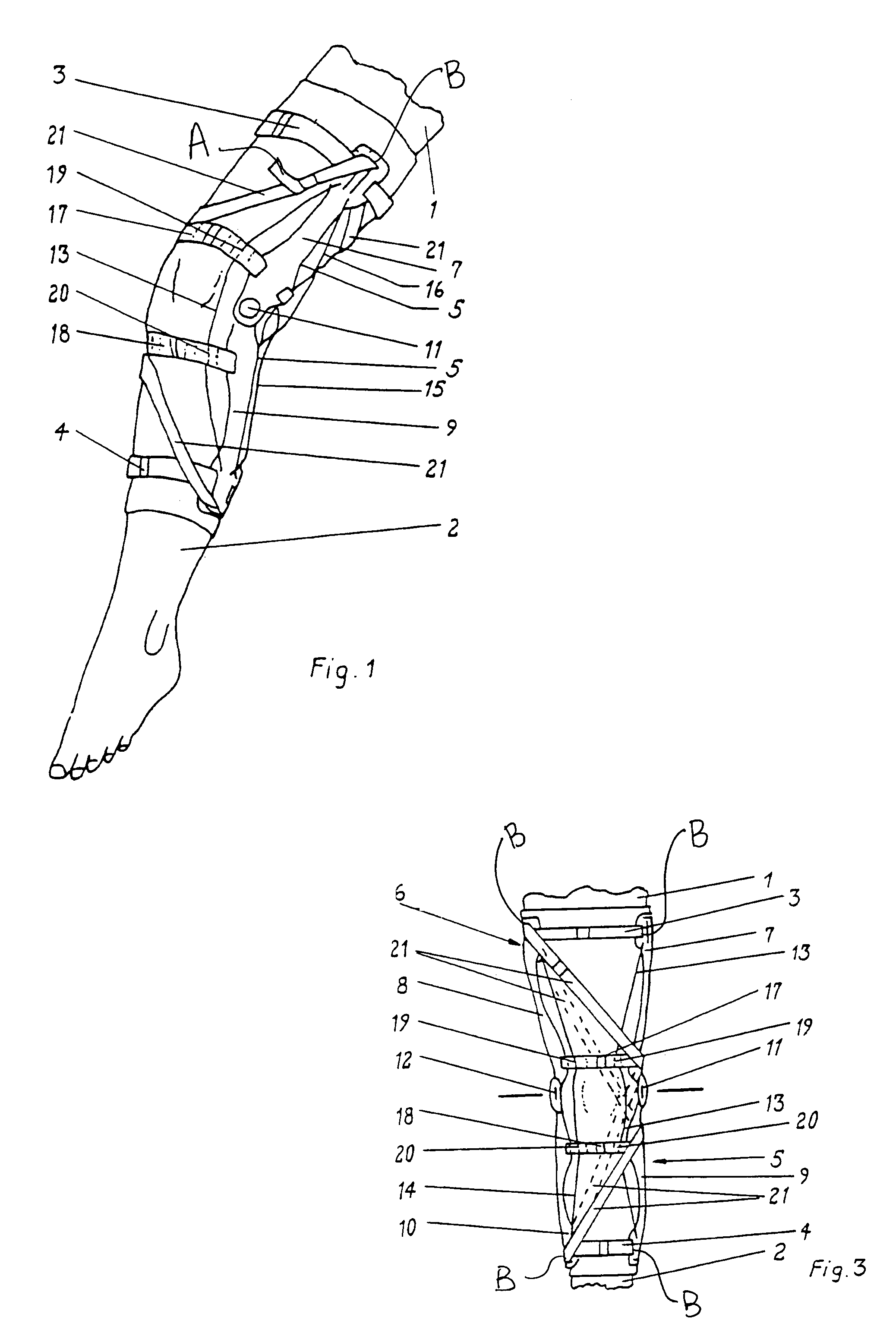
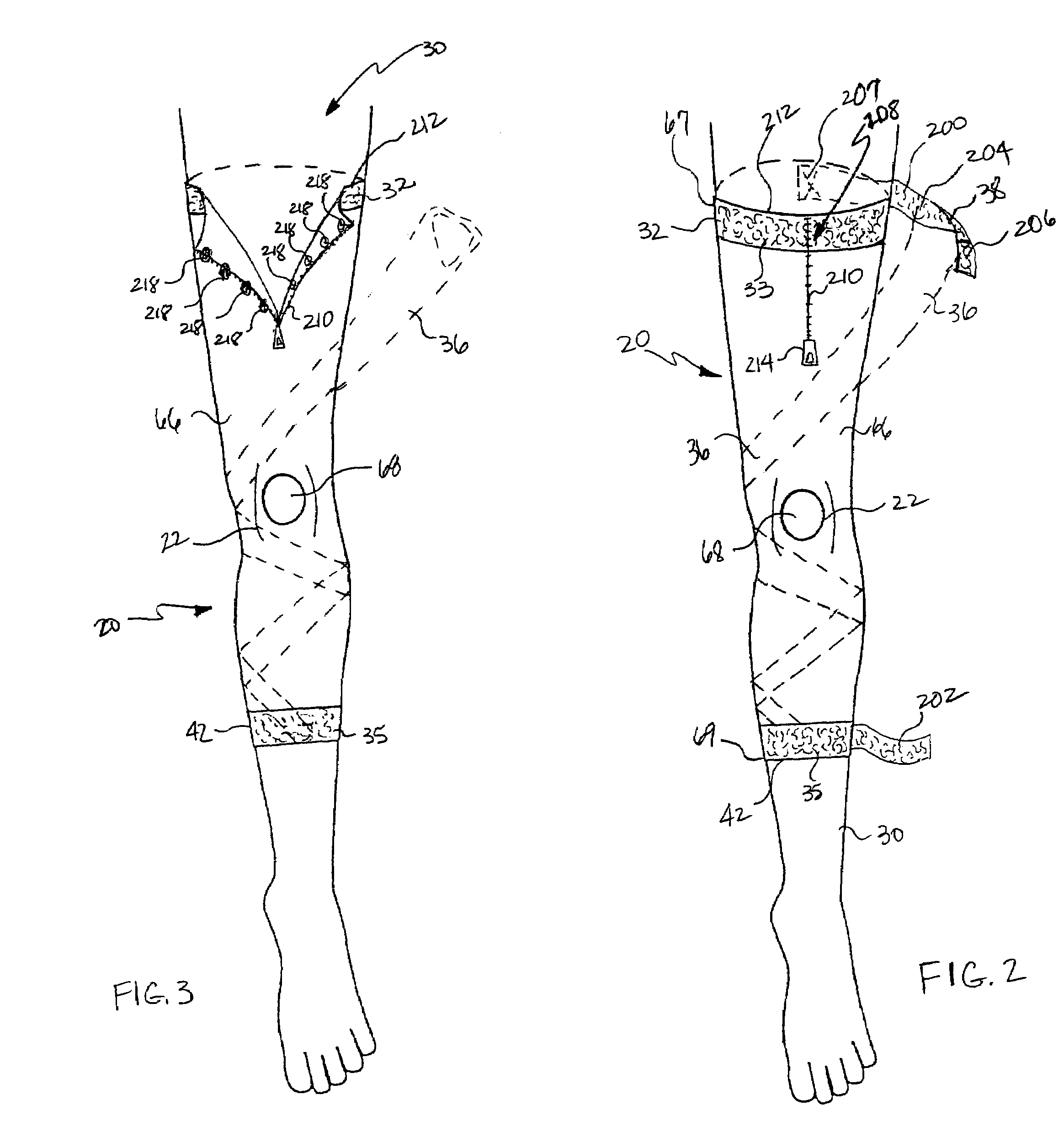
[0048]As shown in FIG. 1, the orthopedic brace 20 of the present invention generally comprises a first bracing member support 32 for positioning about the leg 30, a second bracing member support 42 for positioning about the leg 30, and at least one circumferentially and spirally-wound bracing member 36 sized in length to extend between the first bracing member support 32 and the second bracing member support 42. Both the first bracing member support 32 and the second bracing member support 42 may generally be configured as a collar 26, which is sized to encircle the leg 30 at a given distance above or below the kne...


PUM


Abstract

A lightweight orthopedic brace having no rigid structural elements is constructed from flexible material and is designed primarily to provide for restriction of rotational movement and translation about the target joint by providing flexible bracing members which wind in a circumferentially spiraling manner about a target joint to provide active resistance to axial rotation and translation in the joint. The embodiments of the invention disclosed here provide improved means for placing the invention on the body about a joint, improved means for attachment of bracing members to bracing member supports and improved means for adjusting the length of bracing member to selectively provide for restriction of rotational movement about the target joint.

Description

CROSS REFERENCE TO RELATED APPLICATIONS[0001]This application is a continuation-in-part application of Ser. No. 09 / 004,010, filed Jan. 7, 1998 now U.S. Pat. No. 6,142,965, the contents of which are incorporated herein by reference, and further claims the benefit of U.S. provisional application Ser. No. 60 / 039,104 filed Feb. 25, 1997.BACKGROUND OF THE INVENTION[0002]1. Field of the Invention[0003]This invention relates generally to an orthopedic support device for physiological joints, and more specifically to an improved non-rigid orthopedic appliance and method for construction of a flexible orthopedic bracing system designed to limit both rotational and translational motion about the joints of human or animal limbs, especially around joints such as the knee.[0004]2. Description of Related Art[0005]Functional bracing of physiological joints, particularly the human knee joint, is a phenomenon of relatively recent origin. Substantial interest and effort in the bracing of knees, in pa...

Claims


Application Information

Patent Timeline
Patent Type & Authority Patents(United States)
IPC IPC(8): A61F13/00
CPCA61F5/0104A61F5/0106A61F5/0109A61F2005/0179
Inventor MATHEWSON, PAUL R.
Owner MATHEWSON PAUL R
Why Eureka
Try Eureka