
Method, use and device concerning cladding tubes for nuclear fuel and a fuel assembly for a nuclear pressure water reactor

a technology of nuclear fuel and cladding tubes, which is applied in the direction of reactor fuel elements, instruments, surveying and navigation, etc., can solve problems such as damage risk, and achieve the effects of improving creep properties, good creep properties, and increasing fe-conten

Active Publication Date: 2009-01-06
WESTINGHOUSE ELECTRIC SWEDEN
View PDF11 Cites 3 Cited by
  • Summary
  • Abstract
  • Description
  • Claims
  • Application Information

AI Technical Summary

Benefits of technology

"The present invention relates to a method of producing a cladding tube with good properties using a Zr-based alloy containing Nb. The method involves heating the alloy to a high temperature and then cooling it down to room temperature. The resulting cladding tube has improved resistance against damage caused by PCI and reduced risk of hydride formation. The method also involves annealing the cladding tube at a specific temperature and for a specific time to achieve a degree of recrystallization. The resulting cladding tube has good ductility, low creep rate, and low tendency to crack or grow in response to neutron radiation. The method involves forming a bar of the alloy, heating it, extruding it into a billet, and cold rolling it to a tube. The resulting cladding tube has good properties and is suitable for use in high-temperature environments."

Problems solved by technology

It has however become clear that also for tubes of this kind there is a risk of damages.

Method used


Image

  • Method, use and device concerning cladding tubes for nuclear fuel and a fuel assembly for a nuclear pressure water reactor
  • Method, use and device concerning cladding tubes for nuclear fuel and a fuel assembly for a nuclear pressure water reactor

Examples


Embodiment Construction

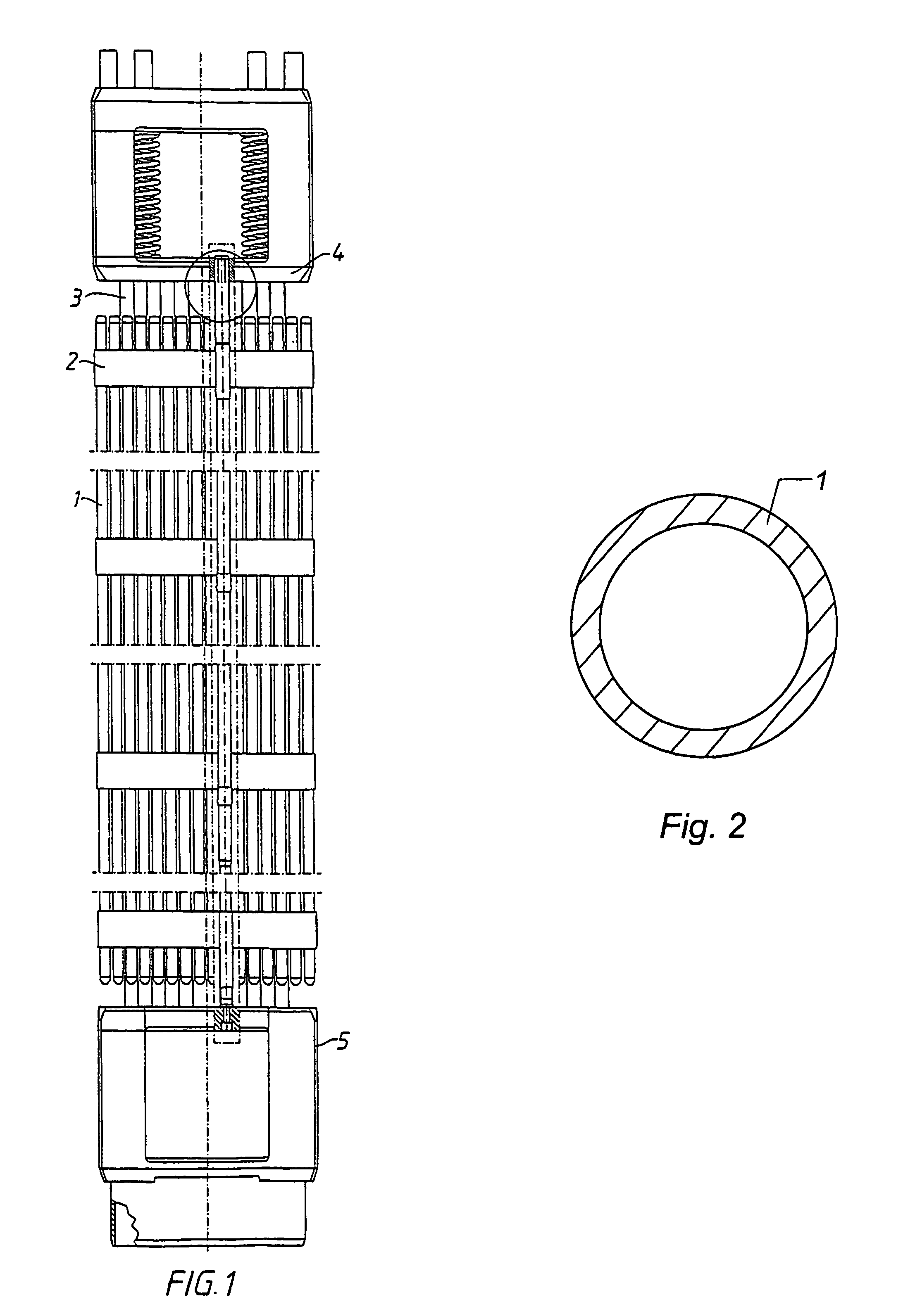
[0039]FIG. 1 shows schematically a fuel assembly for a PWR. The fuel assembly comprises a top plate 4 and a bottom plate 5. Between the top plate 4 and the bottom plate 5 a plurality of guide tubes 3 for control rods extend. Furthermore, the fuel assembly comprises a plurality of cladding tubes 1. These cladding tubes 1 thus contain a nuclear fuel material and are thereby called fuel rods. In this kind of fuel assembly for PWR, the fuel rods do not reach all the way to the top plate 4 and to the bottom plate 5. The fuel rods are kept in position in the fuel assembly with the help of spacers 2.

[0040]FIG. 2 shows schematically a cross-section through a cladding tube according to the invention. The cross-section shows the cladding tube strongly enlarged. In reality, the cladding tube is of a dimension and of a length which are suitable for use in a PWR. The cladding tube comprises a cylindrical tube component 1. In the shown case, the cylindrical tube component 1 constitutes the whole ...


PUM

PropertyMeasurementUnit
temperatureaaaaaaaaaa

Abstract

A method of producing a cladding tube for nuclear fuel for a nuclear pressure water reactor includes forming a tube which at least principally consists of a cylindrical tube component of a zirconium-based alloy, where the alloying element, except for zirconium, which has the highest content in the alloy is niobium, wherein the niobium content in weight percent is between about 0.5 and about 2.4 and wherein no alloying element, except for zirconium and niobum, in the alloy, has a content which exceeds about 0.2 weight percent. The cladding tube is then annealed such that the tube component is partly but not completely recrystallized. The degree of recrystallization in the tube component is higher than about 40% and lower than about 95%. A fuel assembly for a nuclear pressure water reactor also has a plurality of such cladding tubes.

Description

CROSS-REFERENCE TO RELATED APPLICATIONS[0001]This application is entitled to the benefit of and incorporates by reference essential subject matter disclosed in International Application No. PCT / SE2003 / 001685 filed on Oct. 30, 2003 and Swedish Patent Application No. 0203198.7 filed on Oct. 30, 2002.FIELD OF THE INVENTION[0002]The present invention concerns cladding tubes for nuclear fuel for a nuclear pressure water reactor. More precisely, the invention concerns such cladding tubes which are formed of a Zr-based alloy which contains Nb. The invention concerns, inter alia, a method. According to the method, a tube is formed which at least principally consists of a cylindrical tube component of a Zr-based alloy, where the alloying element, except for Zr, which has the highest content in the alloy is Nb, wherein the Nb content in weight percent is between 0.5 and 2.4.[0003]The invention also concerns a cladding tube as such, a use of a cladding tube and a fuel assembly for a nuclear pr...

Claims


Application Information

Patent Timeline
Patent Type & Authority Patents(United States)
IPC IPC(8): C22F1/18G21C19/00C22C16/00G21C3/07
CPCC22C16/00C22F1/186G21C3/07G21Y2002/103Y10T29/49391G21Y2004/10G21Y2004/201G21Y2004/40Y02E30/40G21Y2002/104Y02E30/30
Inventor DAHLBACK, MATSHALLSTADIUS, LARS
Owner WESTINGHOUSE ELECTRIC SWEDEN
Learn More