
Eureka
For R&D, Eureka makes reading and utilizing patents & technical documents easy.
Eureka AIR
Designed for self-driven R&D workflows. Generate viable solutions, solve complex R&D challenges, empower your innovation with AI.

Eureka Materials
Designed for material experts only. Revolutionize your material R&D, from search, analyze, to developing new materials.

TechResearch
Generate reliable direction feasibility study reports for your R&D in just a few steps.

TechSeek
Discover and master advanced knowledge NOW. Basics, ideas, possibilities, all at once.

TechMind
As an expert in R&D Theories, TechMind can generates customized viable solutions instantly.

TechRisk
Analyze your overall solution with one click, know your potential R&D risks in advance.

TechMonitor
Get weekly tech updates, stay abreast of the latest tech innovations and key insights.
Fluidic extraction of microdissected samples
- Summary
- Abstract
- Description
- Claims
- Application Information
AI Technical Summary
Benefits of technology
Problems solved by technology
Method used
Image

Examples
example 1
[0070]For a typical geometry it can be assumed that the film carrier has dimensions of 1 cm. by 1 cm. and that the double sided tape thickness is 100 microns. The resulting enclosed volume will be only 10 mm3 or 10 microliters. At a rotational velocity of 1,000 rpm-30,000 the forces exerted on the enclosed liquid can be sufficient to cause the extraction product to pass through a stop junction that is contiguous with the enclosed volume and be collected in the bottom of a tube.
example 2
[0071]Referring to FIGS. 15A-15D, a single stage extraction device with a pump is depicted. Referring to FIG. 15A, this single stage extraction device includes a base laminate 1510. The base laminate 1510 includes an exit port 1520.
[0072]Referring to FIG. 15B, this single stage extraction device includes a middle laminate 1530. The middle laminate 1530 includes a first orifice defining a pump area 1540. The middle laminate 1530 includes a second orifice defining a reaction area 1550. The reaction area 1550 can correspond to a three-dimensional extraction chamber. The pump area 1540 is connected to the reaction area 1550 via a first capillary 1560. A second capillary 1570 is also connected to the reaction area 1550. The middle laminate area 1530 can be made of a sheet of polymer having a first sticky side and a second sticky side, thereby defining a double adhesive layer.
[0073]Referring to FIG. 15C, this single stage extraction device includes a top laminate 1580. The top laminate 15...
example 3
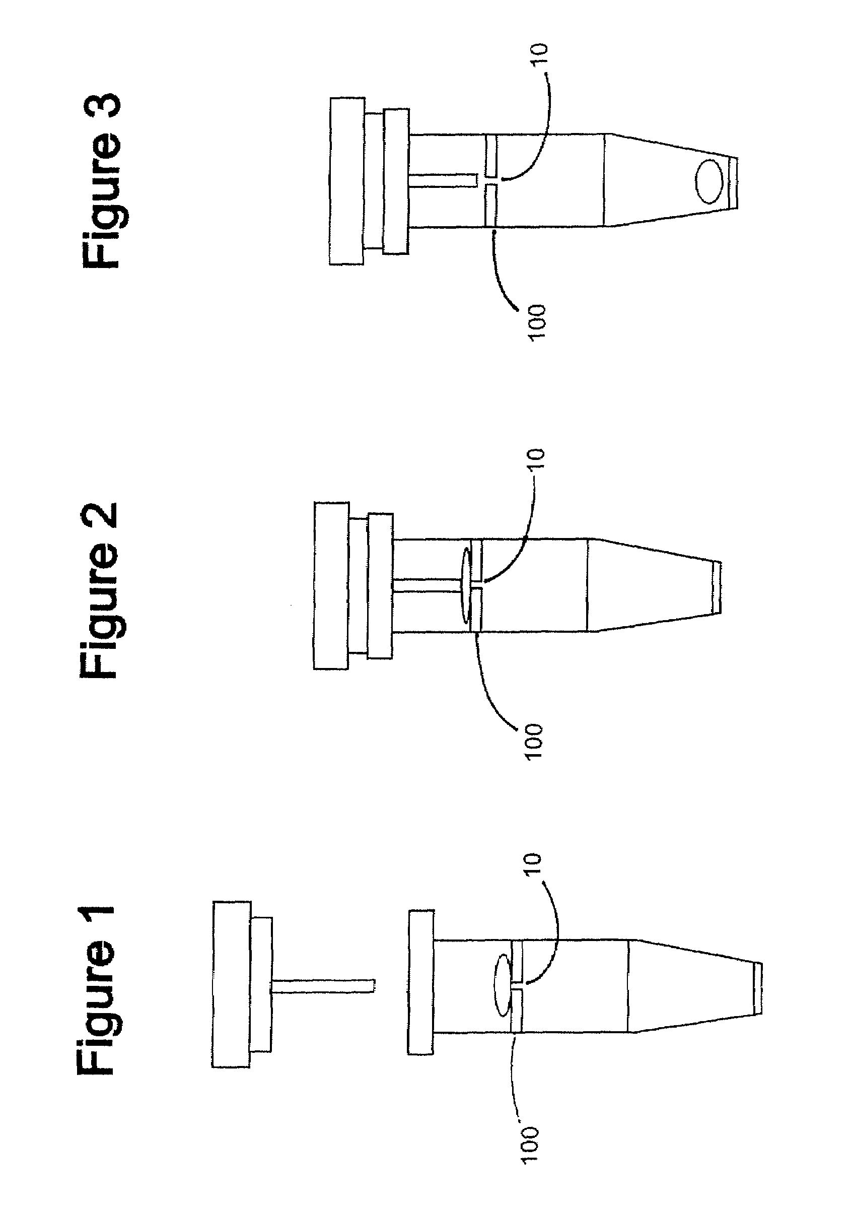
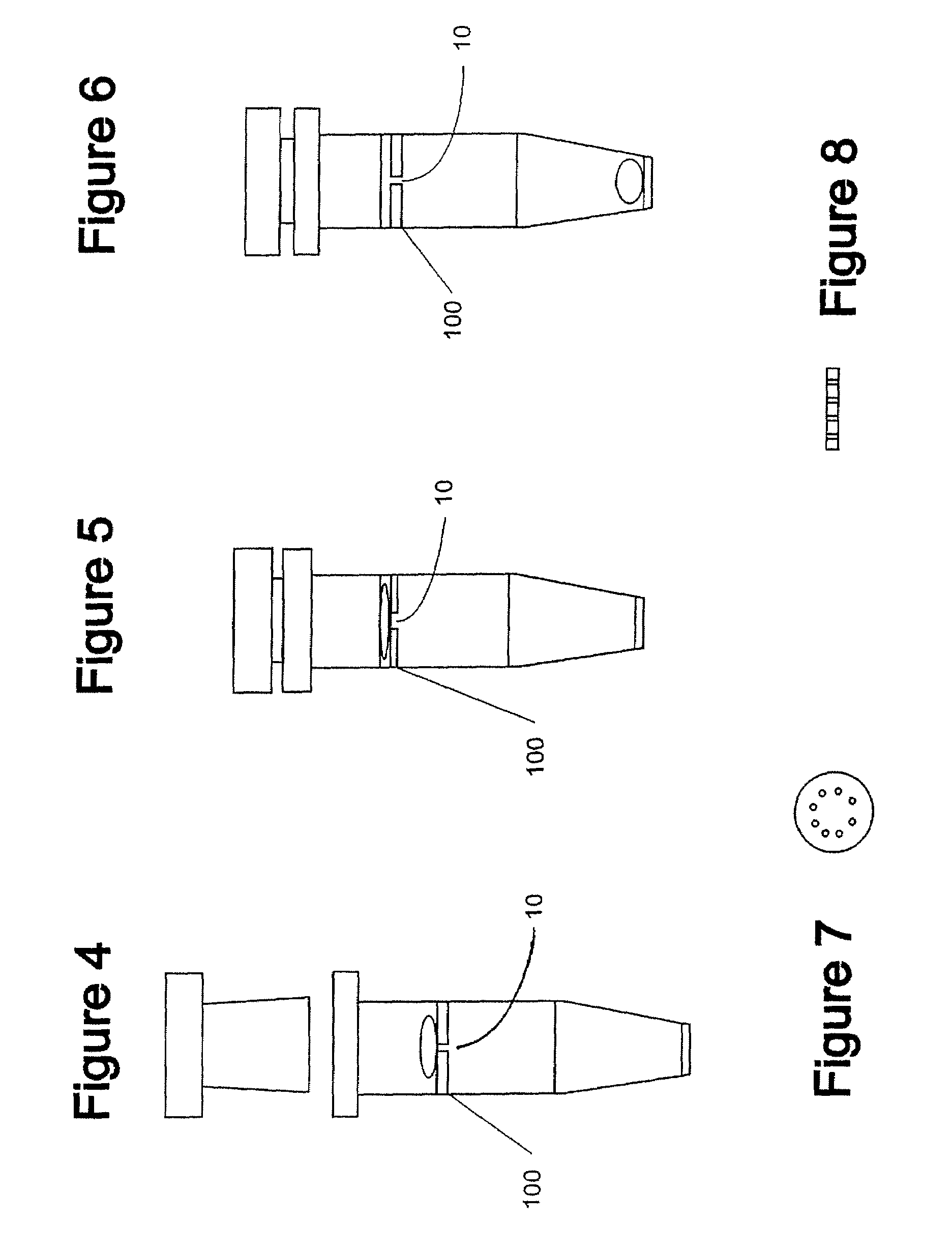
[0076]Referring now to FIGS. 16-22, another single stage extraction device and a method for manufacture thereof will now be described. The device will be described first, then the component parts of the device will be described, then the process of making the device will be described, and then the process of operating the device will be described.
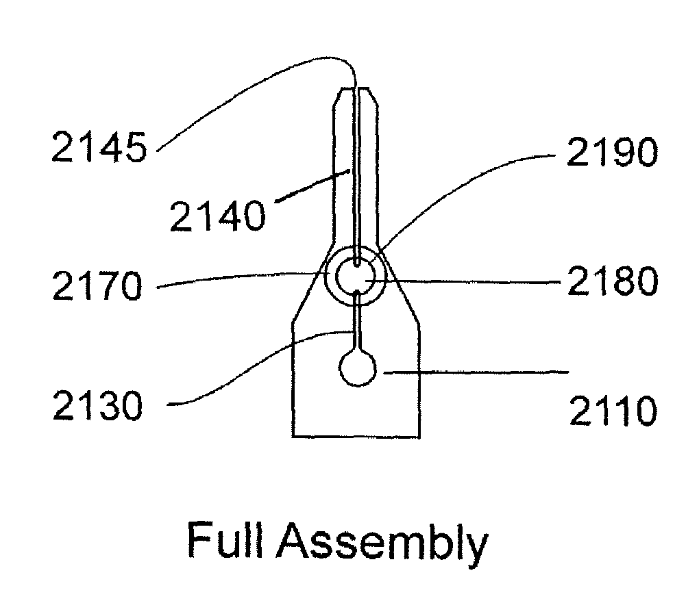
[0077]Referring to FIG. 21E, the assembled single stage extraction device is depicted. This device includes a spacer 2170 that defines in-part an extraction chamber 2180. More generically, the extraction chamber 2180 can be termed a reaction chamber. The extraction chamber 2180 is coupled to first capillary 2130. The first capillary 2130 is coupled to a fill port 2110. The extraction chamber 2180 is also coupled to a second capillary 2140. It can be appreciated that the spacer 2170 overlies and is aligned with the two capillary stop junction holes 2160. Thus, the interior of the spacer 2170 defines the extraction chamber 2180. The spacer 21...
PUM
| Property | Measurement | Unit |
|---|---|---|
| Volume | aaaaa | aaaaa |
| Biological properties | aaaaa | aaaaa |
Abstract
Description
Claims
Application Information
 - R&D Engineer
- R&D Manager
- IP Professional
- Industry Leading Data Capabilities
- Powerful AI technology
- Patent DNA Extraction
Browse by: Latest US Patents, China's latest patents, Technical Efficacy Thesaurus, Application Domain, Technology Topic, Popular Technical Reports.
© 2024 PatSnap. All rights reserved.Legal|Privacy policy|Modern Slavery Act Transparency Statement|Sitemap|About US| Contact US: help@patsnap.com