Exhaust gas-purifying catalyst system

a catalyst system and exhaust gas technology, applied in physical/chemical process catalysts, metal/metal-oxide/metal-hydroxide catalysts, separation processes, etc., can solve the problems of severer and severer regulation value of no/sub>x in exhaust gas, and achieve excellent elimination performance of nox

Active Publication Date: 2009-01-06
CATALER CORP
View PDF11 Cites 23 Cited by
  • Summary
  • Abstract
  • Description
  • Claims
  • Application Information

AI Technical Summary

Benefits of technology

[0009]Accordingly, an object of the present invention is to provide a catalyst excellent in the eliminating performance of NOx.

Problems solved by technology

However, the value of regulation in respect of NOx in the exhaust gas is rendered severer and severer.

Method used


Image

  • Exhaust gas-purifying catalyst system
  • Exhaust gas-purifying catalyst system
  • Exhaust gas-purifying catalyst system

Examples


example 1

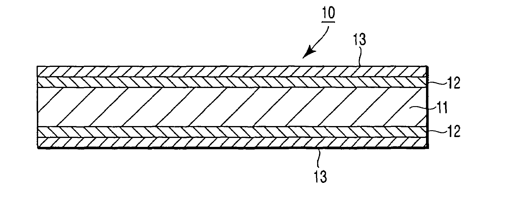
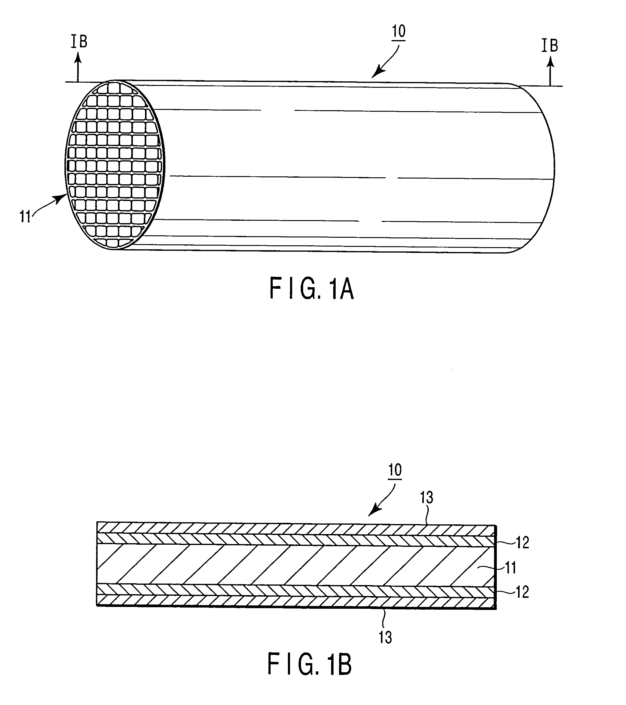
[0041]A cordierite monolithic honeycomb support body (volume: 1.0 L) was coated with a slurry (slurry 1) consisting of an aqueous platinum nitrate solution (0.5 g of Pt), 100 g of an alumina powder, 50 g of a powder of cerium zirconium complex oxide material, 50 g of an aqueous aluminum nitrate solution having a concentration of 50% by weight, and 200 g of water. Then, the coated slurry was dried at 200 to 250° C. for one hour and subsequently baked at 550° C. for 2 hours, forming a second catalyst layer on the surface of the support body. Next, the surface of the second catalyst layer was coated with a slurry (slurry 2) consisting of an aqueous rhodium nitrate solution (0.5 g of Rh), 100 g of an alumina powder, a powder of barium sulfate, 50 g of an aqueous aluminum nitrate solution having a concentration of 50% by weight, and 150 g of water. The coated slurry was dried at 250° C. for one hour and subsequently baked at 550° C. for 2 hours, forming a first catalyst layer on the surf...

example 2

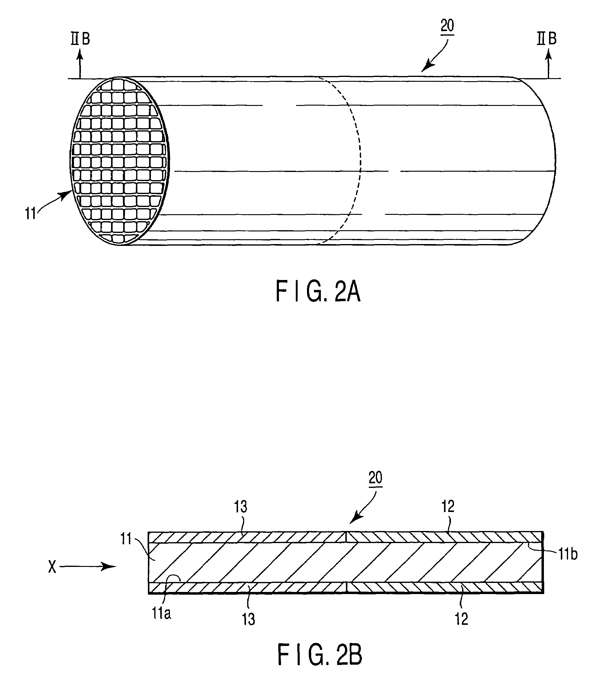
[0042]A cordierite monolithic honeycomb support body (volume: 1.0 L) was coated with the slurry 1 prepared in Example 1, and dried and baked similarly, forming a second catalyst layer. Then, the surface of the second catalyst layer was coated with a slurry (slurry 3) consisting of an aqueous rhodium nitrate solution (0.5 g of Rh), 100 g of an alumina powder, 50 g of a powder of cerium zirconium complex oxide material, a powder of barium sulfate, 50 g of an aqueous aluminum nitrate solution having a concentration of 50% by weight, and 150 g of water, and dried and baked similarly, forming a first catalyst layer on the surface of the second catalyst layer. The powder of barium sulfate was mixed in the slurry 3 such that the first catalyst layer after the baking step contained 0.1 mol / L of barium sulfate. In this way, a desired catalyst system of a double-layer structure was obtained.

example 3

[0043]A cordierite monolithic honeycomb support body (volume: 1.0 L) was coated with a slurry (slurry 4) consisting of an aqueous palladium nitrate solution (0.5 g of Pd), 100 g of an alumina powder, 50 g of a powder of cerium zirconium complex oxide material, a powder of barium sulfate, 50 g of an aqueous aluminum nitrate solution having a concentration of 50% by weight, and 200 g of water. The coated slurry was dried at 250° C. for one hour and subsequently baked at 550° C. for 2 hours, forming a second catalyst layer on the surface of the support body. The barium sulfate powder was mixed in the slurry 4 such that the second catalyst layer after the baking step contained barium sulfate in an amount of 0.1 mol / L. Then, the second catalyst layer was coated with the slurry 2 prepared in Example 1, and dried and baked similarly. In this way, a desired catalyst system of a double-layer structure was obtained.


PUM

PropertyMeasurementUnit
BET specific surface areaaaaaaaaaaa
particle diameteraaaaaaaaaa

Abstract

An exhaust gas-purifying catalyst system is provided with a plurality of catalyst layers including a first and a second catalyst layers, supported on a support structure. The first catalyst layer comes into contact with an exhaust gas stream firstly among the plurality of catalyst layers. The second catalyst layer is provided adjacent to the first catalyst layer. The first catalyst layer contains a first noble metal active component including rhodium, together with a powder of a barely soluble barium compound in an amount of 0.05 mol to 0.2 mol per volume in liter of the support structure. The second catalyst layer contains a second noble metal active component.

Description

BACKGROUND OF THE INVENTION[0001]1. Field of the Invention[0002]The present invention relates to an exhaust gas-purifying catalyst system, and more particularly, to an exhaust gas-purifying catalyst system, which is excellent in the capability of eliminating nitrogen oxides in exhaust gases.[0003]2. Description of the Related Art[0004]In recent years, the regulation of exhaust gas of motor vehicles is being made stricter, increasing the necessity for further decreasing the amounts of hydrocarbons (HC), carbon monoxide (CO) and nitrogen oxides (NOx) in the exhaust gases.[0005]Catalysts having a catalyst active component consisting of a noble metal such as platinum (Pt) carried on a porous carrier such as alumina, which in turn is supported on a heat resistant support structure such as cordierite have been widely used to purify the exhaust gas from a motor vehicle. The supported catalyst noted above is called a 3-way catalyst because the catalyst can oxidize CO and HC and reduce NOx i...

Claims


Application Information

Patent Timeline
Patent Type & Authority Patents(United States)
IPC IPC(8): B01D50/00B01J23/00B01J27/02B01J27/053F01N3/00B01D53/94F01N3/10B01J23/58B01J23/63B01J35/04B01J37/02F01N3/28
CPCB01D53/9422B01J23/58B01J23/63B01J37/0244B01D2255/1021B01D2255/1023B01D2255/1025B01D2255/2042B01D2255/20715B01D2255/407B01D2255/9022B01J37/0234
Inventor KAWAI, MASAAKIMIZUKAMI, TOMOHITOSATO, YASUNORI
Owner CATALER CORP
Why Eureka
Try Eureka