Magnetic field sensor apparatus

a sensor and magnetic field technology, applied in the direction of instruments, galvano-magnetic hall-effect devices, digital computer details, etc., can solve the problems of angle errors and errors that can occur

Active Publication Date: 2009-01-06
INFINEON TECH AG
View PDF10 Cites 116 Cited by
  • Summary
  • Abstract
  • Description
  • Claims
  • Application Information

AI Technical Summary

Problems solved by technology

By the arrangement of the Hall probes at great distance from each other, however, a bad or unfavorable matching results, so that the Hall probes have deviations from each other in their magnetic sensitivities.
Since a relationship of two magnetic fields present at the respective probe locations is determined in the calculation of an angle, angle errors may develop as a result of the variation in magnetic sensitivity and of the unfavorable matching.
But if a mismatch of the probes or Hall sensors changes over the life and / or operation of the Hall probe arrangement, an error can occur as a result of the varying magnetic sensitivities of the Hall probes that cannot be eliminated.

Method used


Image

  • Magnetic field sensor apparatus
  • Magnetic field sensor apparatus
  • Magnetic field sensor apparatus

Examples


first embodiment

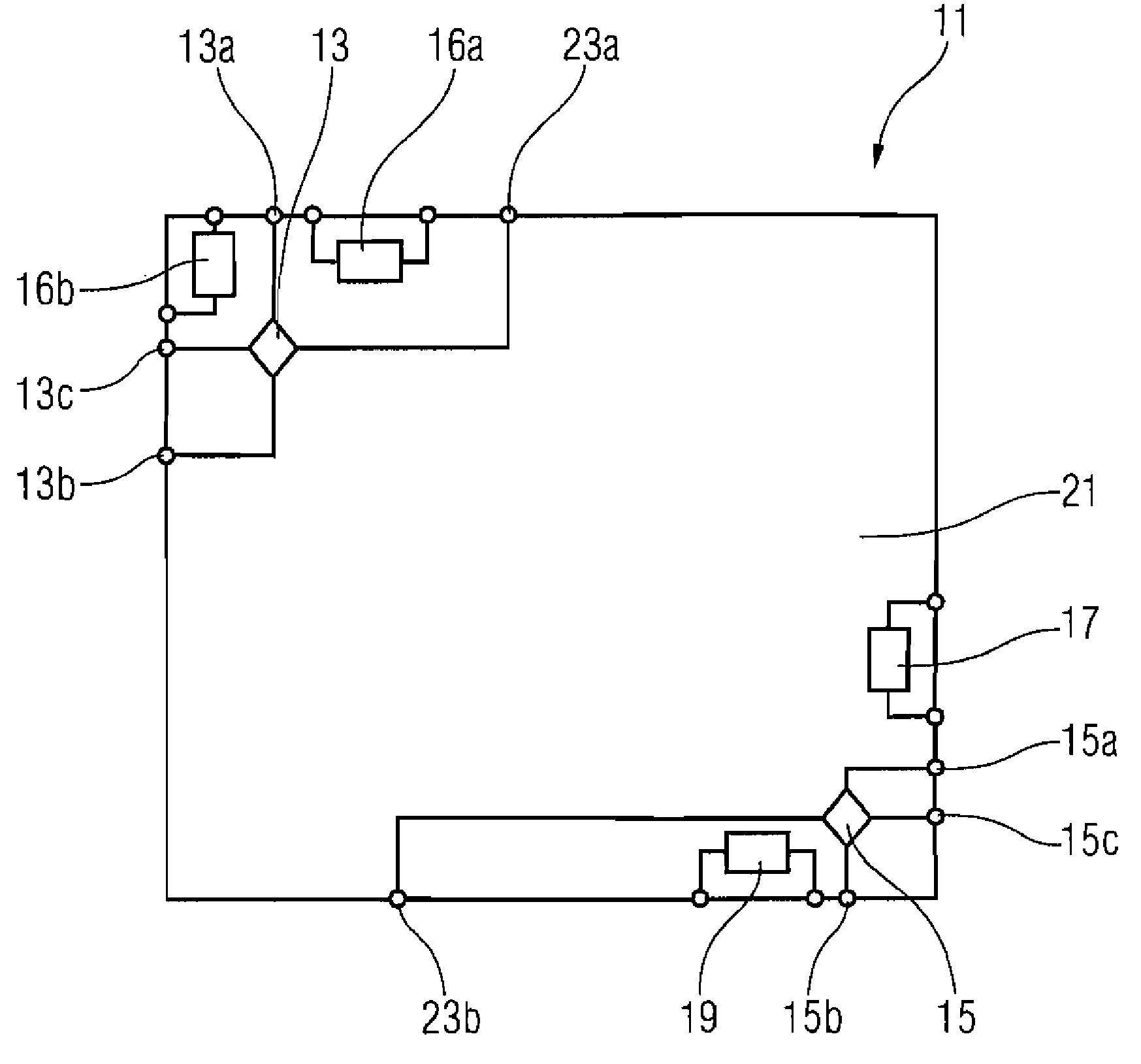
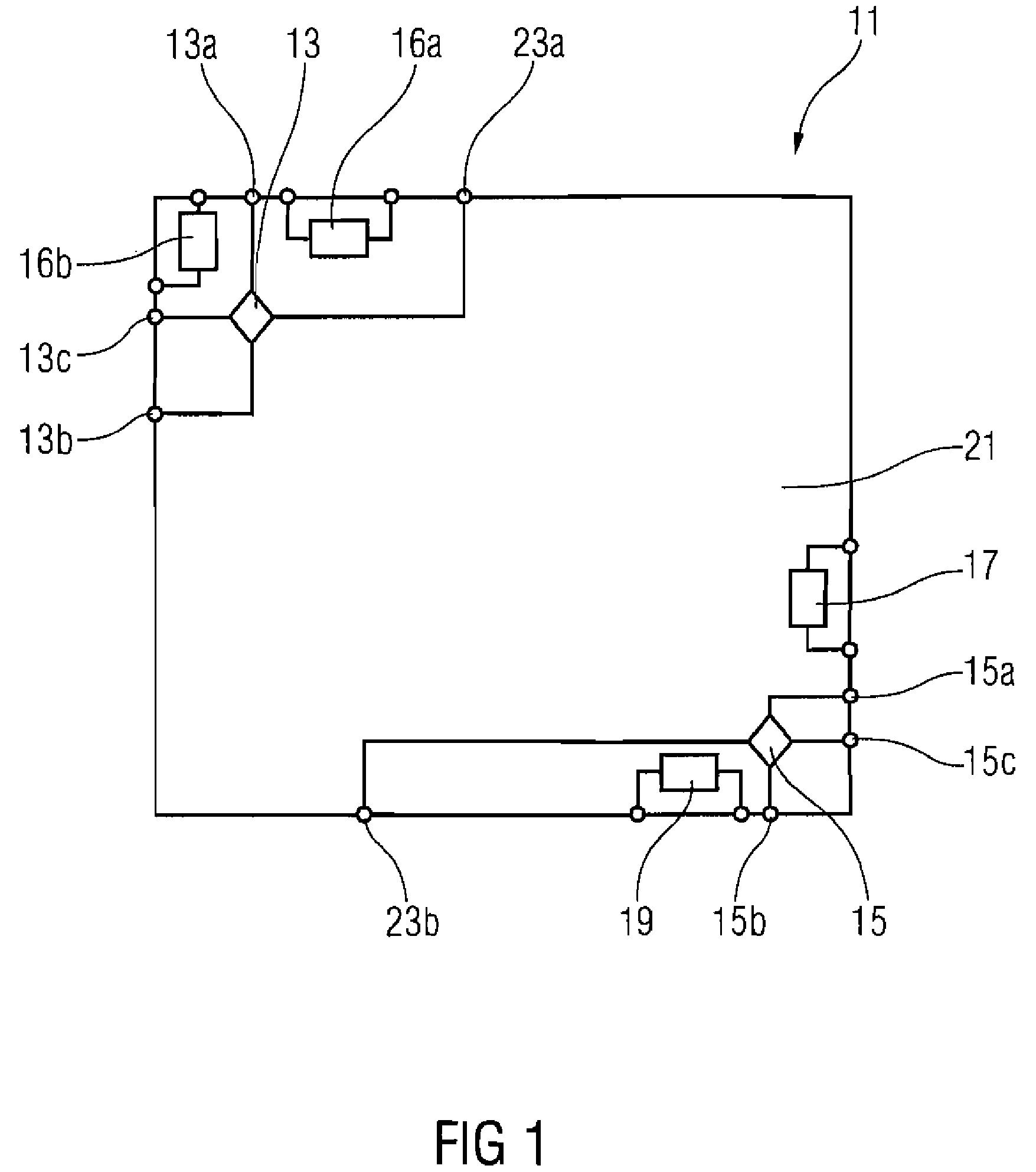
[0023]The magnetic field sensor apparatus 11 according to the present invention thus provides, apart from output signals of the Hall sensors 13, 15, which are tapped as voltages between the terminals 13c, 23a and 15c, 23b, respectively, also the first temperature measurement signal, the first stress measurement signal, the second temperature measurement signal and the second stress measurement signal. In a downstream evaluation means not shown in FIG. 1, based on the output signals of the Hall sensors 13, 15, the temperature measurement signals and the stress measurement signals, a relation or relationship between a magnetic field at the first Hall sensor 13 and the second Hall sensor 15 thus may be determined.

[0024]Since the magnetic field sensor apparatus 11 according to a first embodiment of the present invention additionally provides the temperature measurement signals and the stress measurement signals at the terminals on the substrate 21, the evaluation means downstream to the...

second embodiment

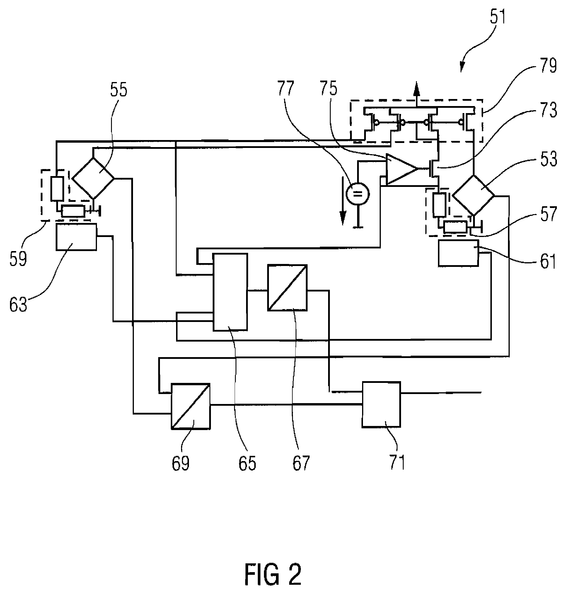
[0029]In the following, a construction of a magnetic field sensor apparatus 51 according to the present invention will be explained in FIG. 2. The magnetic field sensor apparatus 51 or Hall sensor apparatus 51 according to an embodiment of the present invention comprises a first Hall sensor 53, a second Hall sensor 55, a first stress sensor 57, a second stress sensor 59, a first temperature sensor 61, a second temperature sensor 63, a difference calculation means 65, a first analog-digital converter 67, a second analog-digital converter 69, a DSP (digital signal processor) 71, an adjustment transistor 73, an operational amplifier 75, a reference voltage source 77 and a current mirror circuit 79.

[0030]The first Hall sensor 53 is connected at a first terminal to a first output terminal of the current mirror circuit 79 and at a second terminal to a ground terminal. Furthermore, the first Hall sensor 53 is connected at a third terminal to a first input of the second analog-digital conve...


PUM

PropertyMeasurementUnit
angleaaaaaaaaaa
angleaaaaaaaaaa
distanceaaaaaaaaaa

Abstract

A magnetic field sensor apparatus includes a first magnetic field sensor and a second magnetic field sensor, arranged on a substrate in a spaced manner from each other, a first temperature sensor with an output for a first temperature sensor signal, a second temperature sensor with an output for a second temperature sensor signal, a first stress sensor with an output for a first stress sensor signal, and a second stress sensor with an output for a second stress sensor signal, wherein the first temperature sensor and the first stress sensor are arranged more closely to the first magnetic field sensor or at a location identical with the first magnetic field sensor, and the second temperature sensor and the second stress sensor are arranged more closely to the second magnetic field sensor than to the first magnetic field sensor or at a location identical with the second magnetic field sensor.

Description

[0001]This application claims priority from German Patent Application No. 10 2006 045 141.4, which was filed on Sep. 25, 2006, and is incorporated herein in its entirety by reference.TECHNICAL FIELD[0002]An embodiment of the present invention relates to a magnetic field sensor apparatus on a substrate, and particularly to a magnetic field sensor apparatus comprising two magnetic field sensors.BACKGROUND[0003]For determining a position and / or a rotation direction of a transmitting object, such as a permanent magnet, angular sensors on the basis of Hall probes and / or on the basis of magnetic field probes are employed. To this end, several Hall probes are placed in the corners on a chip. If the transmitting object and / or the permanent magnet is rotated above the chip, the Hall probes arranged on the chip each detect a different field and are capable of calculating the angular position of the magnet on the basis of the detected fields. Since the Hall probes depend on detecting the inhom...

Claims


Application Information

Patent Timeline
Patent Type & Authority Patents(United States)
IPC IPC(8): G01R33/02G01B7/00G01L1/12G01R33/07G01B7/30
CPCG01R33/07G01R33/075G01R33/1207
Inventor AUSSERLECHNER, UDO
Owner INFINEON TECH AG
Why Eureka
Try Eureka