Cable-stayed bridge cable force automatic monitoring method and device

A cable-stayed bridge cable force and bridge cable force technology, which is applied in the field of automatic monitoring of cable-stayed bridge cable force, can solve the problems of difficult replacement of sensors, complex devices, and large errors in test results, and achieve the effect of simple structure

Inactive Publication Date: 2007-10-17
CHONGQING JIAOTONG UNIVERSITY
View PDF0 Cites 22 Cited by
  • Summary
  • Abstract
  • Description
  • Claims
  • Application Information

AI Technical Summary

Problems solved by technology

At present, there are mainly two methods for monitoring the cable force during the operation period. One is the spectrum method, which achieves the purpose of monitoring the cable force by monitoring the frequency of the cable, but it has the disadvantages of complex devices and difficulty in real-time monitoring. For bridges with good protection measures and many vibration reduction measures, the error of the test results is large; the second is to install the pressure sensor at the anchor head. This method has the advantages of intuitiveness and reliability, but it also has the fatal disadvantage that it is difficult to replace the sensor after its service life

Method used


Image

  • Cable-stayed bridge cable force automatic monitoring method and device
  • Cable-stayed bridge cable force automatic monitoring method and device

Examples


Embodiment 1

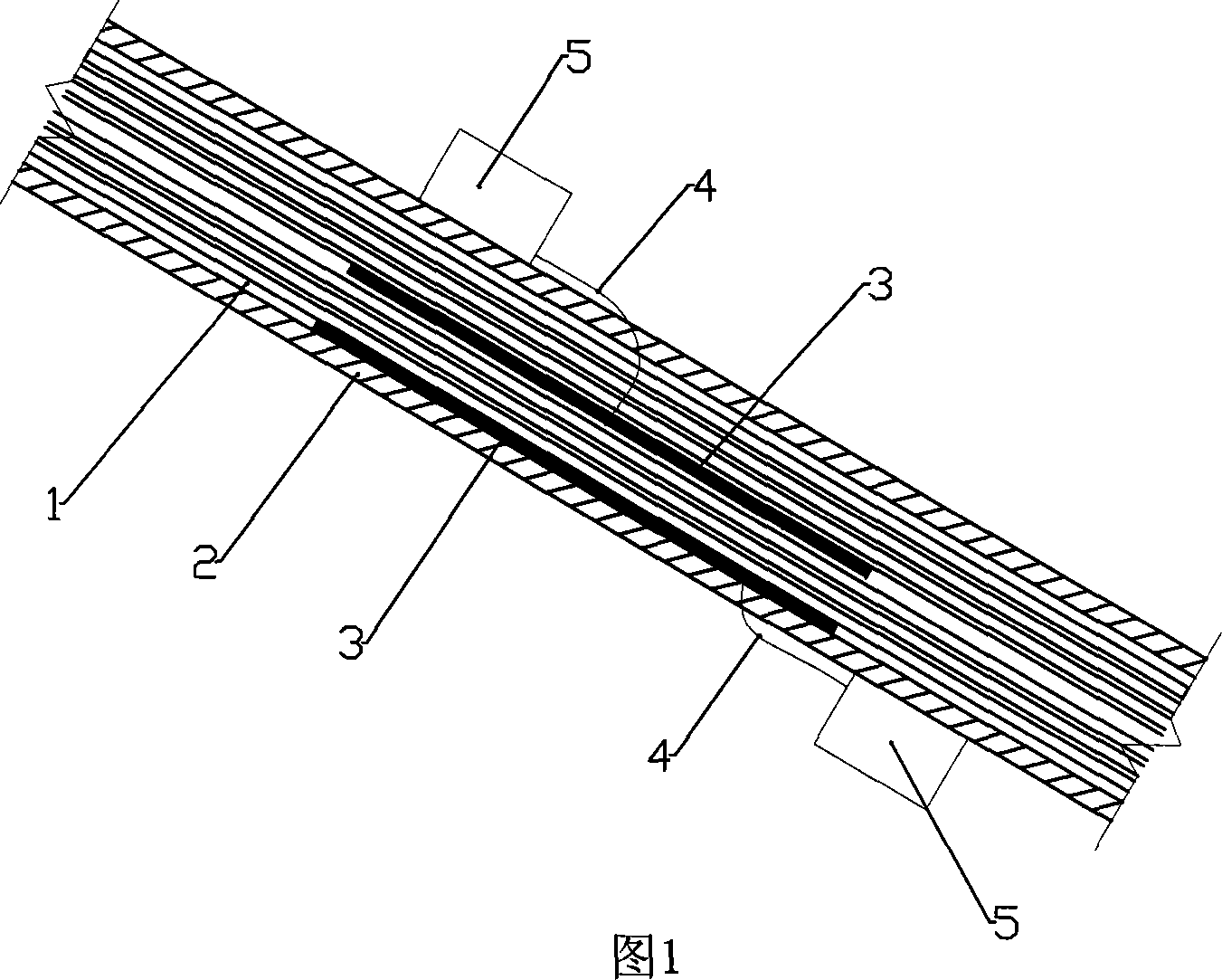
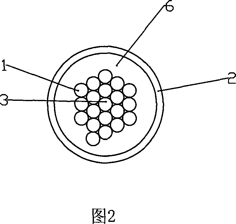
[0014] As shown in Figure 1 and Figure 2, the cable-stayed bridge cable force automatic monitoring device includes an optical fiber grating sensor 3 attached to the PC steel strand 1 forming the cable as a stress sensor for measuring the stress of the cable, and a fixed On the display instrument 5 of the polyethylene protective casing 2 , the fiber grating sensor 3 is connected to the input end of the display instrument 5 through the wire 4 passing through the casing 2 . The optical fiber grating sensor transmits the electrical signal of the cable force to the display instrument 5 through the wire 4, and the display instrument 5 realizes the automatic display of the cable force. There is an anti-corrosion material 6 between the dragline and the sleeve, and the hole on the sleeve 2 for passing the lead 4 is also subjected to anti-corrosion treatment.

[0015] It is understandable that it can also be directly connected to a computer’s data acquisition card through a wire, and th...

Embodiment 2

[0018] A method for monitoring the cable force of a cable-stayed bridge, comprising the steps of:

[0019] (1) Through the calculation and analysis of the internal force of the bridge, combined with the convenience of repair and maintenance, determine the reasonable position to install the cable force monitoring device on the stay cable; (about 3 to 5 meters above the bridge deck is appropriate)

[0020] (2) Paste a fiber grating sensor on the cable at the corresponding position to obtain the stress value of the cable;

[0021] (3) Open a hole at the cable casing corresponding to the position corresponding to the sensor, lead out the electric wire, and carry out anti-corrosion treatment at the opening, and connect it with the display instrument outside the casing to display the stress change of the cable, and / or be connected with a computer for statistics and analysis of cable force changes.

[0022] In step (1), determine the position that best represents the cable force an...


PUM


Abstract

The invention discloses a method for monitoring automatically cable force of cable-stayed bridge, which comprises the following steps: (1) determining a reasonable position on cable-stayed bridge for fixing cable force monitoring device by computing and analyzing bridge inner force and combining simultaneously maintenance and convenience for maintaining; (2) pasting stress sensor on the corresponding position of cable, so as to realize monitor of cable force; (3) opening a hole at cable casing having a corresponding force measurement device, leading out a wire for connecting with the display instrument fixed on the casing, thereby realizing automatic display of cable force, or performing statistic and analysis by computer. An automatic monitoring device is also provided. The cable force monitoring method is capable of real-time monitoring cable force, and replacing monitoring system simply.

Description

technical field [0001] The invention belongs to the field of bridges, in particular to a method and a device for automatically monitoring cable force of cable-stayed bridges. Background technique [0002] The cable-stayed cables of cable-stayed bridges are the main stress-bearing components, and the diseases caused by severe corrosion are common, seriously affecting the structural safety and durability of cable-stayed bridges in normal use. At present, the repair, maintenance and replacement of stay cables are relatively weak. Especially due to reasons such as design and cost, the lower part of the main girder of a general cable-stayed bridge is not designed with special inspection and maintenance facilities. The cables of cable-stayed bridges are life cables. Once the cables are corroded and broken, the whole bridge may collapse. Therefore, it is very important to monitor the cable force of the cable in real time. At present, there are mainly two methods for monitoring t...

Claims


Application Information

Patent Timeline
Patent Type & Authority Applications(China)
IPC IPC(8): G01L5/10
Inventor 周建庭曾德荣
Owner CHONGQING JIAOTONG UNIVERSITY
Why Eureka
Try Eureka