Ultrasonograph

a technology of ultrasonograph and sonic wave, which is applied in the direction of tomography, applications, instruments, etc., can solve the problems of inability to cross ultrasound beams in ultrasound measurement, inability to apply a method of generating tomographic images using a combination of ultrasound beams, and inability to achieve the effect of improving the diagnostic image quality and increasing the apparatus scal

Inactive Publication Date: 2009-01-06
HITACHI LTD
View PDF14 Cites 52 Cited by
  • Summary
  • Abstract
  • Description
  • Claims
  • Application Information

AI Technical Summary

Benefits of technology

[0007]To solve the above-described problem, the object of the present invention is to provide a technique with which a tomographic image can be collected using a two-dimensional array ultrasound probe. Another object of the present invention is to provide a technique with which the image quality of a diagnostic image can be improved using a two-dimensional array ultrasound probe without increasing the apparatus scale.

Problems solved by technology

However, when an ultrasonic diagnostic apparatus has a two-dimensional probe, including two-dimensionally arranged transducer elements in a flat surface, and an aperture is formed by concentric multiple rings on the two-dimensional ultrasound probe, the direction of forming an ultrasound beam is limited to the direction of a normal line the probe surface.
Further, because an ultrasonic diagnostic apparatus employing a sparse array technique performs a sector scan with an ultrasound beam without moving the aperture, it is impossible to cross ultrasound beams in the ultrasound measurement.
Accordingly, it was impossible to apply a method of generating a tomographic image using a combination of ultrasound beams.
However, a compound scan using a two-dimensional array probe is not disclosed.

Method used


Image

  • Ultrasonograph
  • Ultrasonograph
  • Ultrasonograph

Examples


embodiment 1

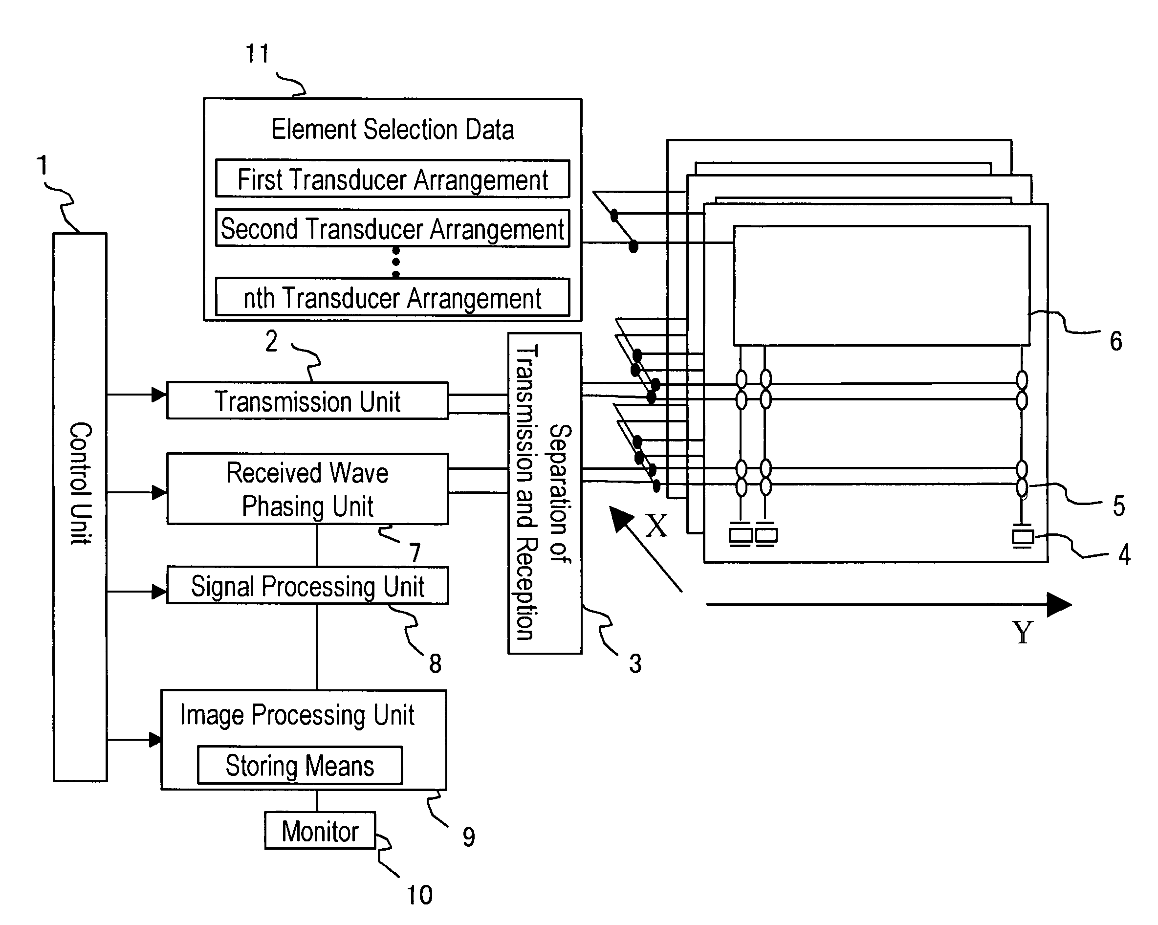
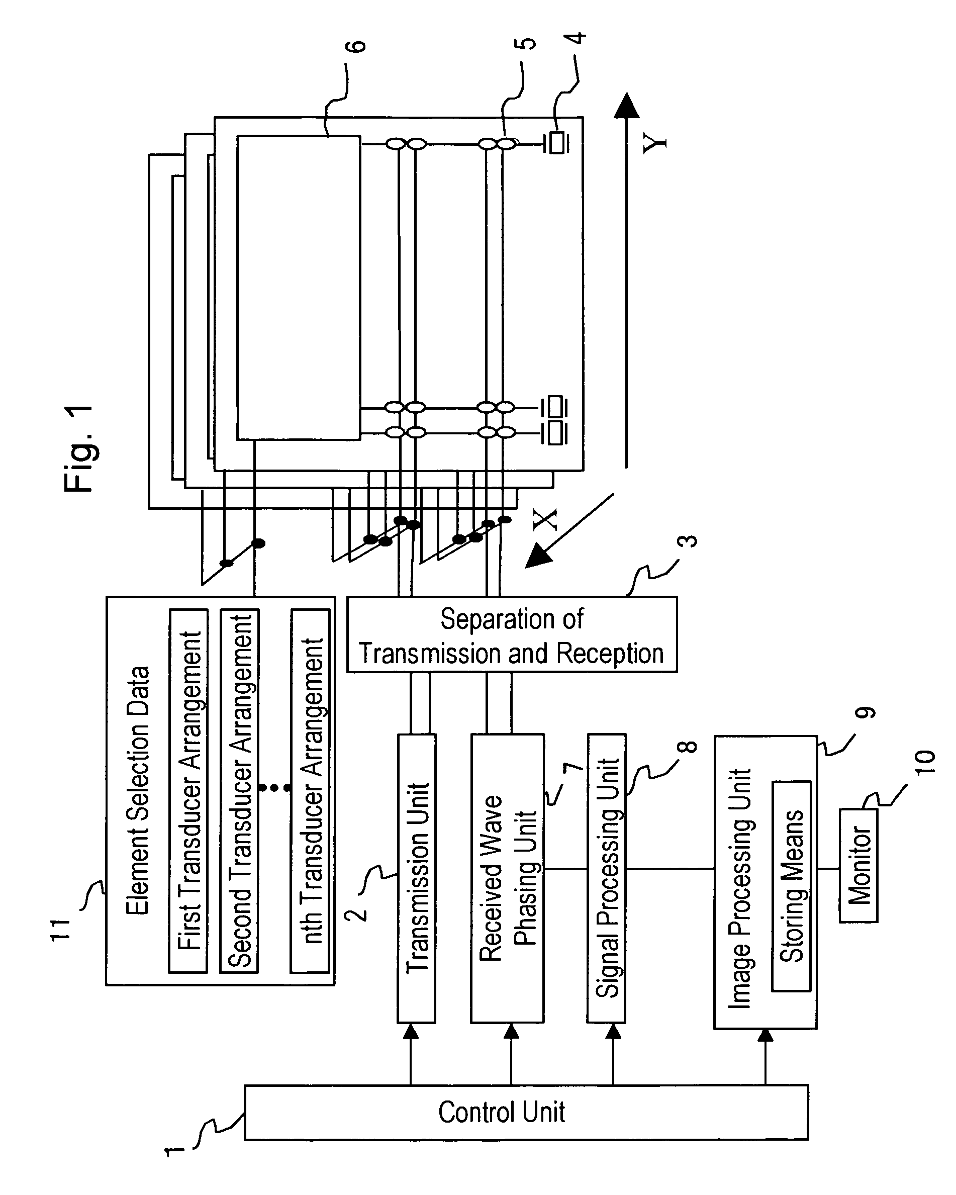
[0016]FIG. 1 shows the structure of an embodiment of an ultrasonic diagnostic apparatus according to the present invention. This ultrasonic diagnostic apparatus is designed to form an ultrasound beam with a two-dimensional transducer array and for scanning the beam to obtain an ultrasound image of a portion under diagnosis inside an object to be examined in real time. The apparatus includes ultrasound transducer 4, element selection data unit 11, transmission unit 2, received wave phasing unit 7, transmission-reception separating circuit 3, signal processing unit 8, image processing unit 9, monitor 10, and control unit 1.

[0017]A probe is designed to transmit and receive an ultrasonic wave inside the object, and for this purpose it has a plurality of two-dimensionally arranged transducers 4, 4, . . . Those transducers 4, 4, . . . are two-dimensionally arranged, with 1 to m elements being arranged in the X direction and 1 to n elements being arranged in the Y direction in a plane.

[001...

embodiment 2

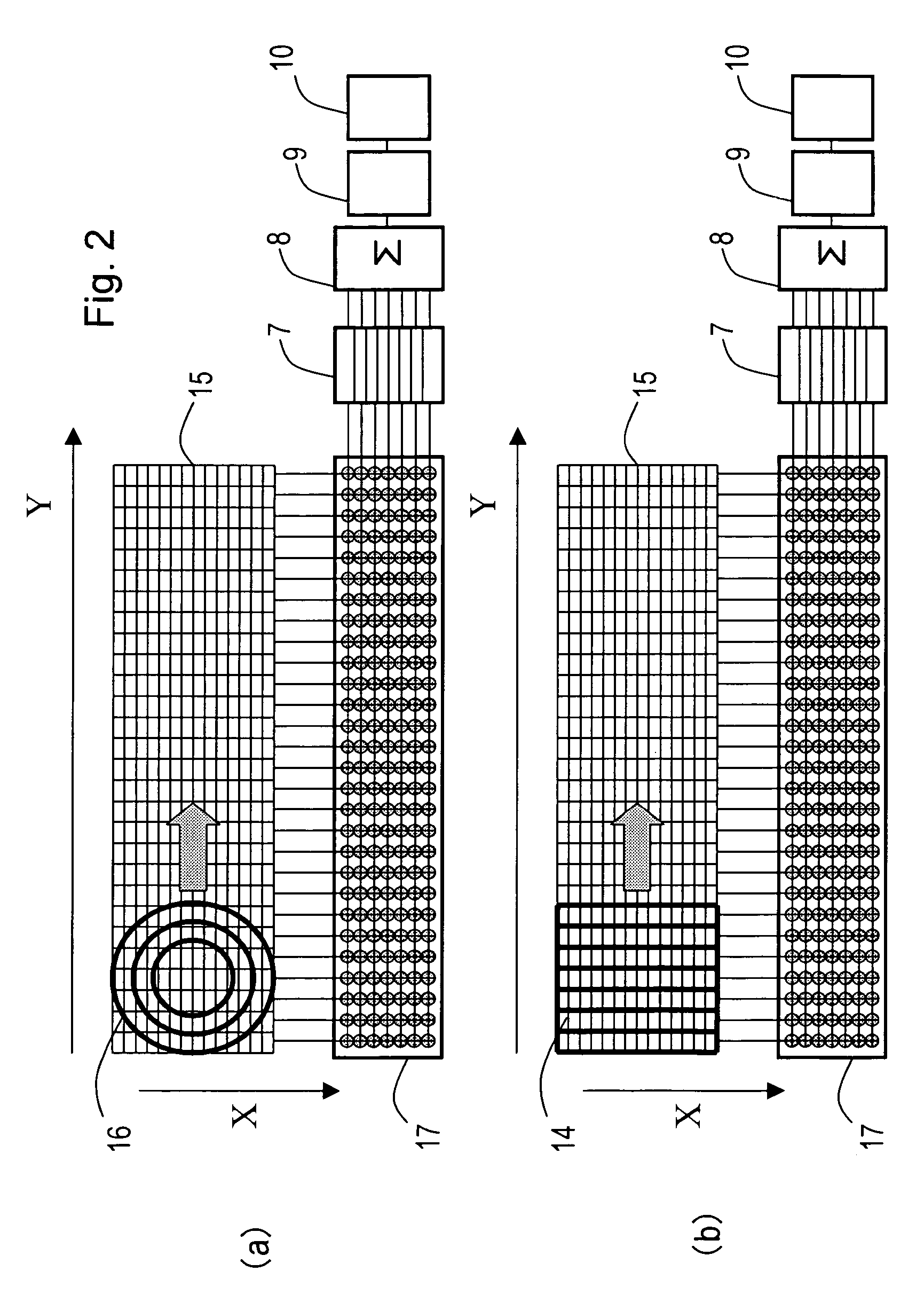
[0044]FIGS. 5(a), 5(b) and 5(c) are diagrams illustrating the structure of an ultrasonic diagnostic apparatus according to an Embodiment 2 of the present invention. Specifically, FIG. 5(a) is a diagram illustrating the structure where a tomographic image is collected by an aperture formed by concentric multiple rings, and FIG. 5(b) is a diagram illustrating the structure where a tomographic image is collected by transducer elements which are bundled into strip shapes. Meanwhile, in the ultrasonic diagnostic apparatus according to Embodiment 2, a larger number of transducer elements 4 is provided than in the two-dimensional array probe according to Embodiment 1, scans of aperture 16 and aperture 14 are performed in both the Y-axis and X-axis directions, and a plurality of ultrasonic tomographic images thus obtained are formed into a three-dimensional ultrasound image. Other structural features are similar to Embodiment 1. Accordingly, in the following description, the three-dimension...

embodiment 3

[0059]FIG. 6 and FIG. 7 are diagrams illustrating the structure of an ultrasonic diagnostic apparatus according to Embodiment 3 of the present invention. Specifically, FIG. 6 is a diagram illustrating collection of tomographic image data using the aperture of a sparse array 16′, and FIG. 7 is a diagram illustrating collection of tomographic image data using the aperture of transducer elements bundled into strip shapes. As an example, according to Embodiment 3, a two-dimensional array probe including 64×64=4096 transducer elements 4 is used. However, the number of transducer elements is not limited to 4096. Further, although a conventional sparse array does not need the array switch 17 in which a plurality of element selecting switches are arranged, transducer element 4 is connected to received wave phasing unit 7 through array switch 17 according to Embodiment 3. With this structure, ultrasound transmission and reception of both sparse array 16′ and of transducer elements 4 bundled ...


PUM


Abstract

An ultrasonic diagnostic apparatus includes an ultrasound probe having two-dimensionally arranged transducer elements for transmitting and receiving ultrasonic waves to an object, a transducer element selector for selecting transducer elements used in transmission and reception, a signal processing unit for applying a delay to a signal received by a selected transducer element, an image processing unit for generating an image based on the output signal of the signal processing unit, and an image display unit. The image processing unit stores a first ultrasound image obtained by a scan of a first transducer arrangement selected by the transducer element selector and a second ultrasound image obtained by a scan of a second transducer arrangement selected by the transducer element selector so as to irradiate an ultrasound beam in a different direction than the beam direction of the first transducer arrangement, and combines the first ultrasound image and the second ultrasound image.

Description

TECHNICAL FIELD[0001]The present invention relates to an ultrasonic diagnostic apparatus, and, more particularly, to an effective technique for using, in a three-dimensional scan of an object, a two-dimensional array probe in which a plurality of transducer elements for transmitting and receiving an ultrasonic wave are two-dimensionally arranged.BACKGROUND OF THE INVENTION[0002]Along with recent developments in the performance of ultrasonic diagnostic apparatuses and in the use of a ultrasound diagnostic techniques, ultrasonic diagnostic apparatuses are being utilized in various fields of diagnosis, and a three-dimensional display of an image is now desired in performing a diagnosis using ultrasound. Usually, it was necessary for displaying a three-dimensional image display to collect a plurality of tomographic images of an object to be examined at a plurality of predetermined distances and to reconstruct a three-dimensional image by joining the outlines of an organ or the like whic...

Claims


Application Information

Patent Timeline
Patent Type & Authority Patents(United States)
IPC IPC(8): G06K9/00A61B8/00A61B8/13
CPCA61B8/13G01S7/52065G01S7/52085G01S15/8925A61B8/483G10K11/345G01S15/8927G01S15/8922Y10S128/922A61B8/4494
Inventor SHINOMURA, RYUICHIKANDA, HIROSHITAMANO, SATOSHI
Owner HITACHI LTD
Why Eureka
Try Eureka