
System for automation of technical processes

a technology of automation system and technical process, applied in the direction of automatic controller, programme control, instruments, etc., can solve the problems of inability to set up such automation without the assistance of specialists, complicated setup of automation on the basis of such software solutions, and high cost, so as to facilitate the user's application development and facilitate the use of his application. , the effect of facilitating the user's development of his application

Active Publication Date: 2009-01-06
RENNER PETER
View PDF25 Cites 16 Cited by
  • Summary
  • Abstract
  • Description
  • Claims
  • Application Information

AI Technical Summary

Benefits of technology

[0019]It can be seen that this classification greatly facilitates the development of the automation task, especially as the event modules and the function modules are automatically placed in the module window upon the choice of visualization objects. If the program start and program end are left aside as obvious, the user only has to be concerned with the choice of the sequence modules.
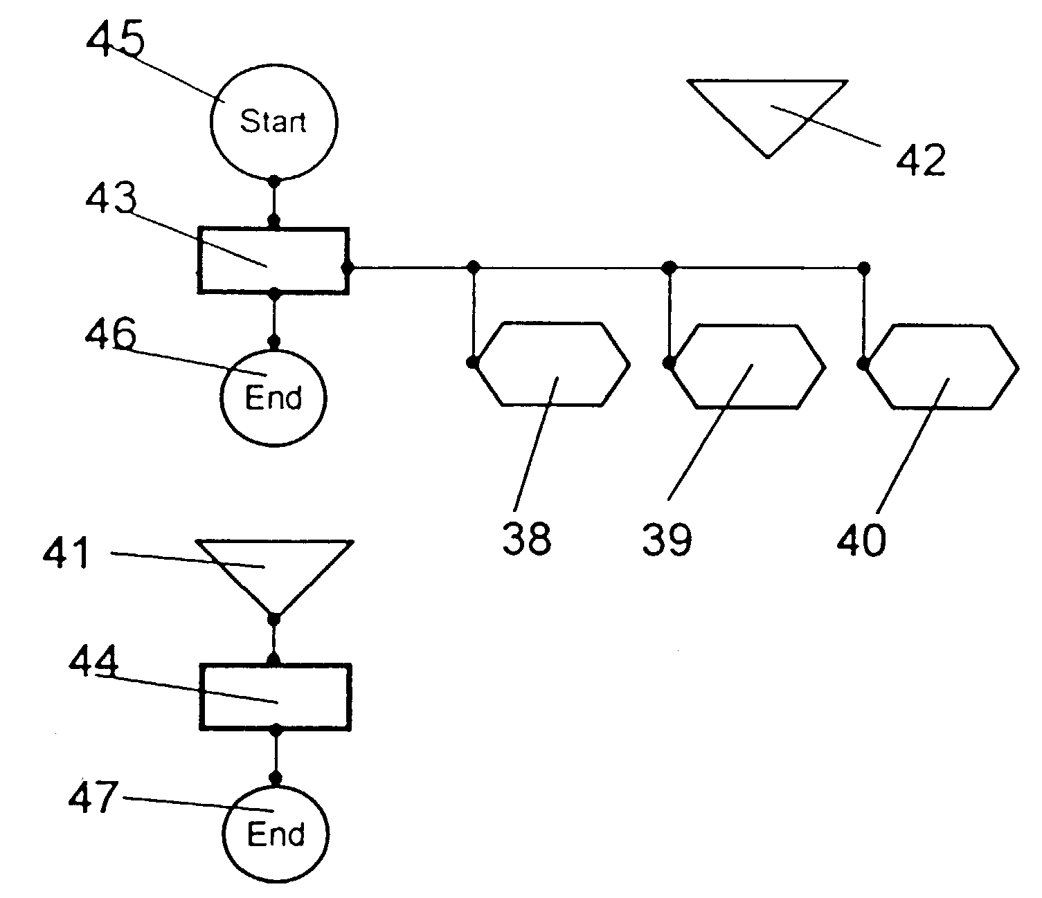
[0020]In further embodiment of the invention it is provided to assign a symbolic figure to each of the sequence, event and function modules. These symbolic figures should be clearly distinct from one another. In conjunction with chaining, which is described further on, they make it easy for the user to recognize the structure of his automation task. If the user pulls a module from the library into the module window, the module will manifest itself as a symbolic figure on the screen surface of the module window. Other modules, as already described, are automatically exhibited when the corresponding visualization object is exhibited. The user can arrange the figures on the screen as he would like to shape the sequence as illustrated in FIGS. 2 and 6.
[0041]The query category contains the instruction “If TYPE [logical operation] then” with the options “If now but not previously then” and “If not then.” This instruction, indeed, contains the command “IF then else,” known per se. The instruction according to the invention is inventive because, with the optional instruction “If now but not previously then,” it contains the possibility of detecting exactly the point in time at which the event arose. Thus the “If [ ] then” construct expands to new dimensions by further facilitating the user's development of his application.
[0042]The known programming languages are text-based. This means that a user will type in the commands that he is newly formulating except for those that he copies from another text region. These steps are time-consuming and error-prone. There is thus a danger of syntax errors. The invention takes a quite novel route in that the script is graphically oriented. The individual components of the script, such as keywords, instructions, variables, constants—in short, script objects—are graphical objects. These graphical objects are in part the subject of the program skeletons of the individual modules. Also, as previously described, further script objects can be taken from the knowledge or library lists and inserted into the script via keywords. The script objects are arranged in line-oriented fashion, so that the graphical script does not look much different from a text-based script. The advantages are obvious because handling is easier. It is further possible to append image-oriented symbols to the text-oriented script objects, so that the language can be still further simplified.

Problems solved by technology

It is not possible to set up such automation without the aid of specialists.
The expense is considerable.
In the view of many users, the setup of automation on the basis of such software solutions is very complicated and demands a long familiarization time.
The expense is considerable.
These solutions did not succeed in bringing about consistency between operating and observing and automation.

Method used


Image

  • System for automation of technical processes
  • System for automation of technical processes
  • System for automation of technical processes

Examples


Embodiment Construction

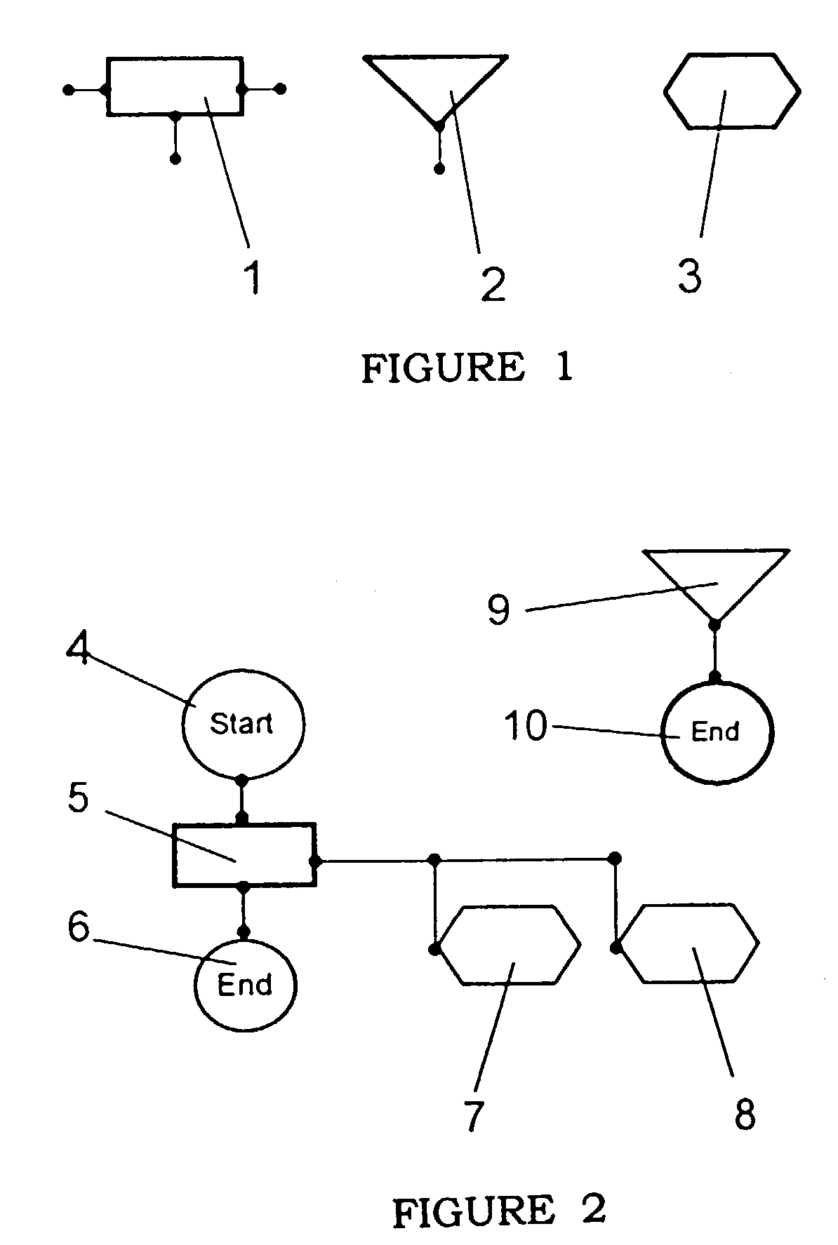
[0052]Referring to FIG. 1 the reference characters have the following meanings:[0053]1 is a geometric figure representing a sequence module;[0054]2 is a geometric figure representing an event module; and[0055]3 is a geometric figure representing a function module.

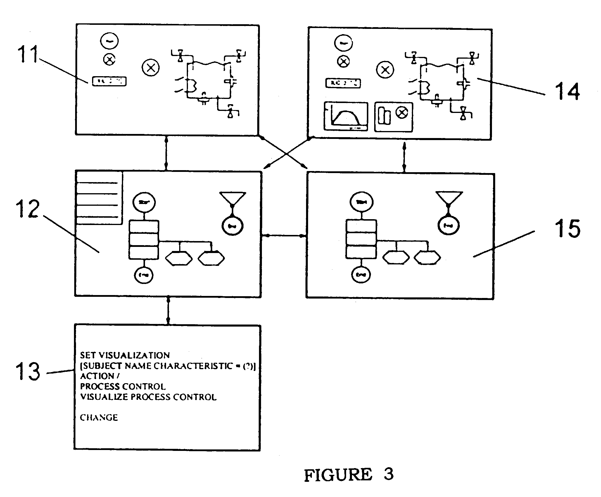
The geometric figures of FIG. 1 represent the control modules and are depicted as graphical objects in the module window 12 of FIG. 3. They can be linked to one another according to specified rules in a way that corresponds to the program sequence. When the graphical object is marked and double-clicked, the configuration window 13, as shown in FIG. 3, opens. The module can now be configured.

[0056]In FIG. 2 the reference characters have the following meanings:[0057]4 is a graphical object of the start module;[0058]5 is a graphical object of a sequence module;[0059]6 is a graphical object of an end module;[0060]7 is a graphical object of a function module;[0061]8 is a graphical object of a further function module;[0062]9 is a...


PUM


Abstract

A system for automation of technical processes and / or experiments having a measurement unit and a control unit which are connected to sensors and actuators of the process or of the experimental unit via measurements and control channels, having at least one library that contains visualization objects and control modules, and having software that manages the system. The system enables the user to develop applications without knowledge of programming techniques. Technologists, chemists, scientists using the system no longer need to rely on the aid of programming specialist.

Description

TECHNICAL FIELD[0001]This invention relates to a system for automation of technical processes or experimental procedures having a measurement and control unit connected to sensors and actuators of a process, a library containing visualization objects and control modules together with software managing the system.BACKGROUND OF THE INVENTION[0002]There is a group of products known as “process instrumentation and control systems” on the market. They are often used to control and operate large industrial installations. Such systems work on two tracks. For control tasks they use automation software known as PLC (programmable logic controller) software and PLC programming system. Visualization software independent of the control software is used for operator guidance. Control software and visualization software run in distinct devices: the control software in PLCs or process control devices in a process plane, and the visualization software in the instrumentation and control plane. Theref...

Claims


Application Information

Patent Timeline
IPC IPC(8): G05B11/01G05B15/00G05B19/42G05B19/042
CPCG05B19/0426G05B2219/23084G05B2219/23258G05B2219/23389G05B2219/2612
Inventor RENNER, PETER
Owner RENNER PETER
Learn More