
Method for fault handling in a co-operative workflow environment

a workflow environment and fault handling technology, applied in the field of computer systems, can solve problems such as inability to handle nested scopes, transactions (which fall under backward error recovery mechanisms), and inability to adapt to the situation

Inactive Publication Date: 2009-01-06
INT BUSINESS MASCH CORP
View PDF19 Cites 12 Cited by
  • Summary
  • Abstract
  • Description
  • Claims
  • Application Information

AI Technical Summary

Benefits of technology

The solution enables effective fault handling and recovery in cooperative workflow environments by ensuring faults are correctly propagated and handled, maintaining system performance and preventing resource bottlenecks.

Problems solved by technology

These are specified using proprietary languages and usually do not handle nested scopes.
Transactions (which fall under backward error recovery mechanisms), which have been successfully used in providing fault tolerance to distributed systems, are not suited in such cases because of various reasons.
These transactional systems may not be compliant with each other and may not be willing to do so, given their intrinsic autonomy and the fact that they span different administrative domains.
In addition, locking resources until the termination of the embedding transaction is in general not appropriate for cooperative workflows, still due to their autonomy, and also to the fact that they potentially have a large number of concurrent clients that will not stand extensive delays.
First, there is no centralized global state as different workflow components execute on different nodes and communicate asynchronously with each other. In contrast, in workflows with centralized control, the entire state and all the faults remain localized to that central workflow component.
Second, correct placement of transaction scopes, fault handlers and compensation handlers in co-operating workflows is essential in order to maintain correct semantics of the application. Furthermore, the workflow components generally need to be modified with additional code to correctly forward and handle faults.
Third, different workflow components may execute at different times and have either overlapping or different lifecycles—which means that there is generally no single context available where all faults can be handled. Furthermore, workflow specification languages like BPEL4WS provides “scope” activities to define transaction scopes and associate fault handlers and compensation handlers with them to create a fault handling and recovery context. They also ensure fault recovery semantics in which compensation handlers are invoked in their reverse order of completion of their respective scopes. This complicates fault handling and fault recovery when the different workflow components run at different or overlapping times. A single transaction scope might span across various workflow components and the partitioned scopes (which reside in different workflow components) might have different lifetimes and as a result, their data is no longer available for compensating them. Thus, a mechanism is required to store the data of already completed “transaction scopes” so that it can be used for compensating them in case of a fault.
This is an issue in co-operating workflows with distributed control flow as different workflow components can execute concurrently and forward their results to other workflow components for further processing.
This will result in system resources being held up by the waiting workflow component and the performance of the system will go down over a period of time as the number of faults becomes significant.
Not much work has been done in this area.

Method used


Image

  • Method for fault handling in a co-operative workflow environment
  • Method for fault handling in a co-operative workflow environment
  • Method for fault handling in a co-operative workflow environment

Examples


Embodiment Construction

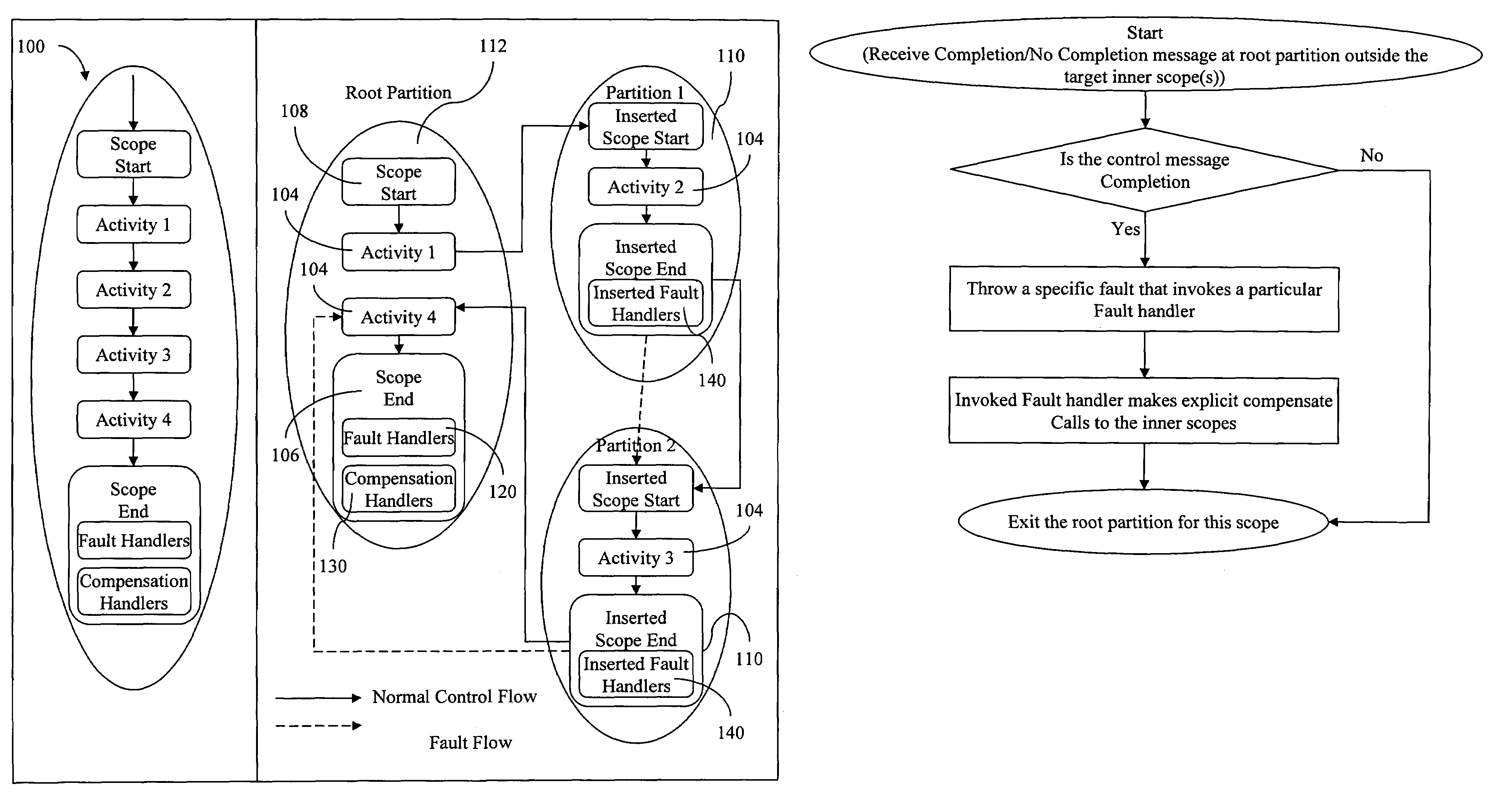
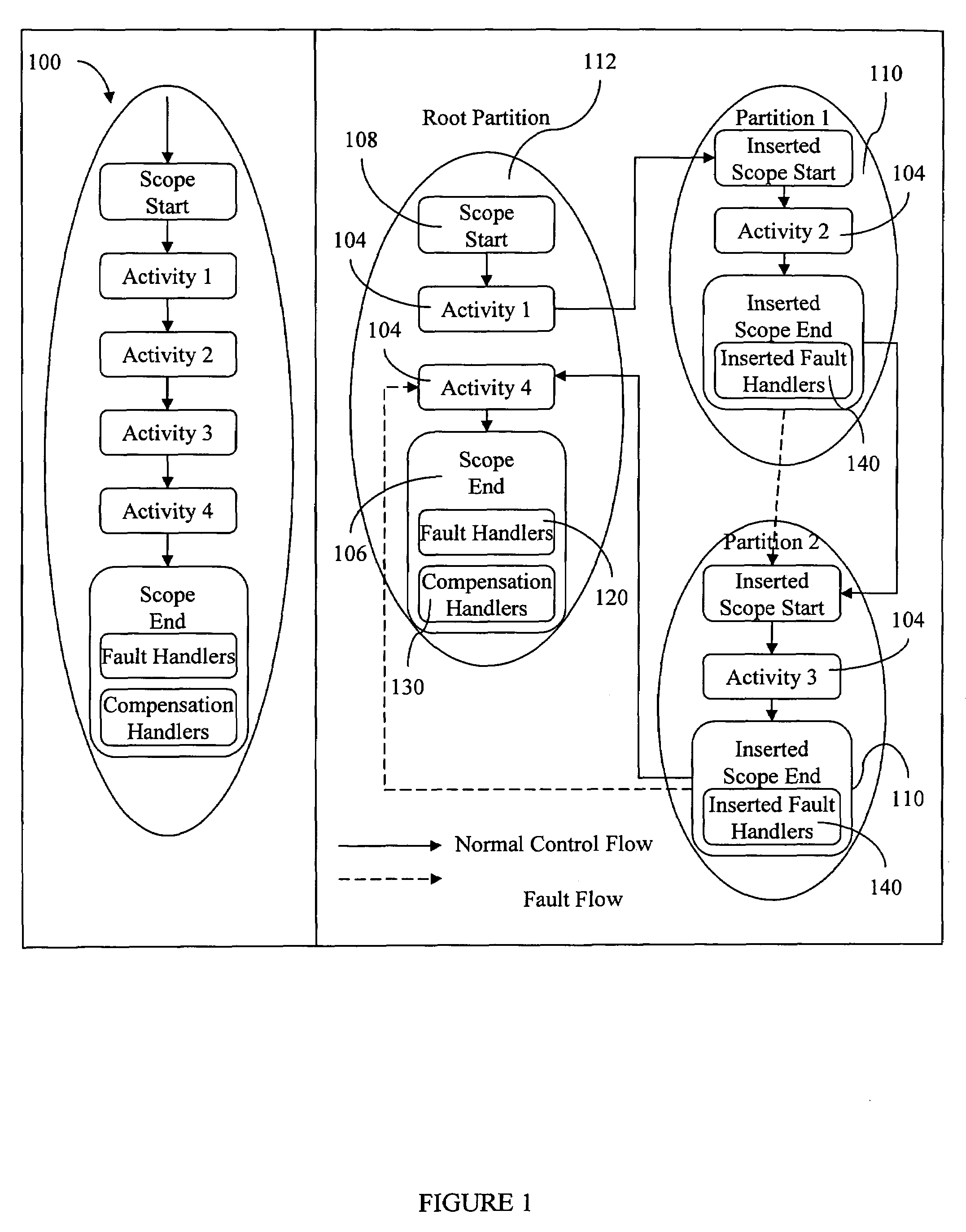
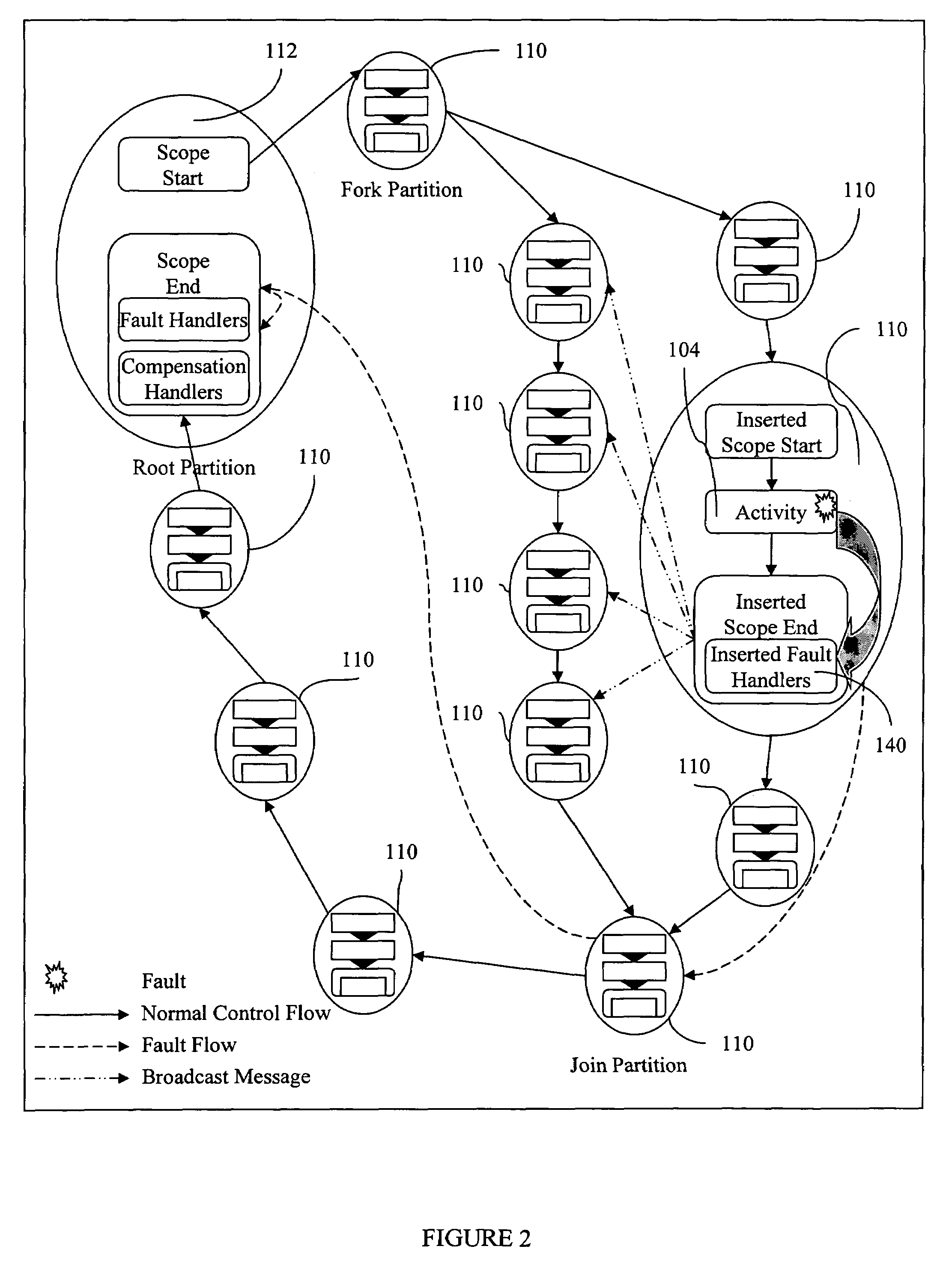
[0027]The embodiments of the invention and the various features and advantageous details thereof are explained more fully with reference to the non-limiting embodiments that are illustrated in the accompanying drawings and detailed in the following description. It should be noted that the features illustrated in the drawings are not necessarily drawn to scale. Descriptions of well-known components and processing techniques are omitted so as to not unnecessarily obscure the embodiments of the invention. The examples used herein are intended merely to facilitate an understanding of ways in which the embodiments of the invention may be practiced and to further enable those of skill in the art to practice the embodiments of the invention. Accordingly, the examples should not be construed as limiting the scope of the invention.

[0028]As mentioned, there is a clear need for more effective techniques for handling faults in cooperative workflow environments. The embodiments of the invention ...


PUM


Abstract

The invention provides a method for fault handling in a co-operative workflow environment that employs a placement strategy for transaction scope and associated fault handlers and compensation handlers across different workfiow components. The method employs a fault propagation scheme for forwarding a fault occurring in any of the workflow components to a fault handler. The method employs a distributed data collection mechanism to facilitate recovery from a fault occurring in any the workfiow components. The method employs a fault recovery mechanism using compensation. The transaction scope defines a transaction boundary and provides a fault handling and a fault recovery context for a set of activities and the transaction scope may be nested inside another transaction scope resulting in outer and inner scopes.

Description

BACKGROUND OF THE INVENTION[0001]1. Field of the Invention[0002]The embodiments of the invention generally relate to computer systems, and, more particularly, to co-operative workflow environments running on those computer systems.[0003]2. Description of the Related Art[0004]Co-operative workflow environments consist of multiple workflow components deployed at different locations in a distributed infrastructure. Each workflow component works co-operatively with other components to complete an overall global task. The workflows communicate directly with each other (rather than through a centralized controller) in an asynchronous manner to transfer data and control when necessary. For example, cross organizational business processes can be implemented using co-operating workflows. Another example is decentralized orchestration of composite web services which is used for either performance benefits (in terms of throughput and response time) or for orchestrating composite web services i...

Claims


Application Information

Patent Timeline
Patent Type & Authority Patents(United States)
IPC IPC(8): G06F11/00
CPCG06F11/0709G06F11/0784G06F11/1474G06F11/0793
Inventor CHAFLE, GIRISH B.CHANDRA, SUNILKANKAR, PANKAJMANN, VIJAY
Owner INT BUSINESS MASCH CORP
Learn More