Drilling device provided with a multi-bladed drilling tool, especially a deep drilling tool

a drilling device and multi-blade technology, applied in the direction of maintenance and safety accessories, turning apparatuses, large fixed members, etc., can solve the problems of blocking or blocking the chip removal channel, limited cross-section of the drilling device,

Inactive Publication Date: 2009-01-13
TBT TIEFBOHRTECHN
View PDF37 Cites 4 Cited by
  • Summary
  • Abstract
  • Description
  • Claims
  • Application Information

AI Technical Summary

Benefits of technology

[0012]Moreover, due to the fact that in this construction a projection projecting circumferentially into the chip space is created, despite a large chip space a surface is formed acting as a guidance zone for the drill and which is e.g. somewhat increased in diameter compared with the standard drill circumference and consequently serves as a work guide. Particularly with an asymmetrical blade arrangement, it absorbs reaction pressures and ensures a precise guidance of the drill in the already formed hole, which renders possible axial precise drilling, particularly with deep drills.
[0013]A further inventive measure for preventing blockages and removal problems with respect to long chips formed, is brought about in that a multiblade drilling tool, considered in an axial plan view on the drill end, has a bend on one of the blades where the two blade sections meet under an angle, which is preferably between 170ø and 120ø. This can e.g. arise in that at some distance from the drill centre the blade bends in the rotation direction or passes with a radius into a new orientation. Thus, the chip space is further enlarged. The bent blade ensures that the chips break more easily and do not arise as a relatively wide, coiled strip which can stick in the removal channels. Instead two tightly juxtaposed, narrower chip strips are formed, which should really still adhere in the centre, but as a result of the different formation conditions the chip can tear longitudinally and also transversely, which leads to a chip pattern corresponding to a short-chip material. This measure can in the case of a two-blade drill e.g. be provided on both blades, so that the drill once again has a symmetrical cutting pattern, but is advantageously only provided on one blade. In this case, as a result of the different cutting geometry, deliberately a transverse force is produced on the drill head, which for a clear engagement presses one of the guide zones onto the hole wall and consequently prevents all guidance problems as a result of the mutual engagement of the drill. Thus, a deliberate asymmetry of the blades is created.

Problems solved by technology

Whereas in the case of single-flute drills having only a single blade, the chip space or chamber formed upstream of the blade and correspondingly also the removal channels are relatively large, with multiblade drills the cross-section thereof is limited.
With long-chip materials, e.g. in the case of steel as opposed to aluminium or cast material, the long, helical chips formed easily lead to blocking or clogging of the chip removal channels.

Method used


Image

  • Drilling device provided with a multi-bladed drilling tool, especially a deep drilling tool
  • Drilling device provided with a multi-bladed drilling tool, especially a deep drilling tool
  • Drilling device provided with a multi-bladed drilling tool, especially a deep drilling tool

Examples


Embodiment Construction

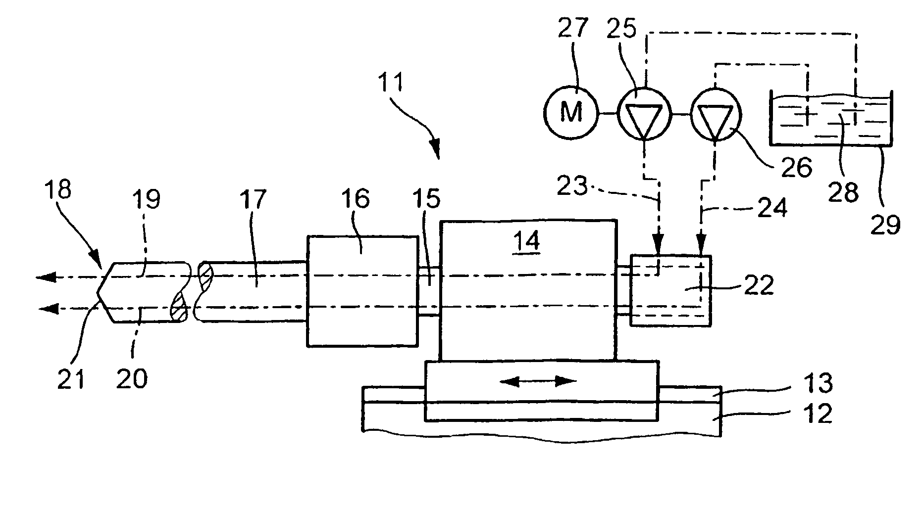
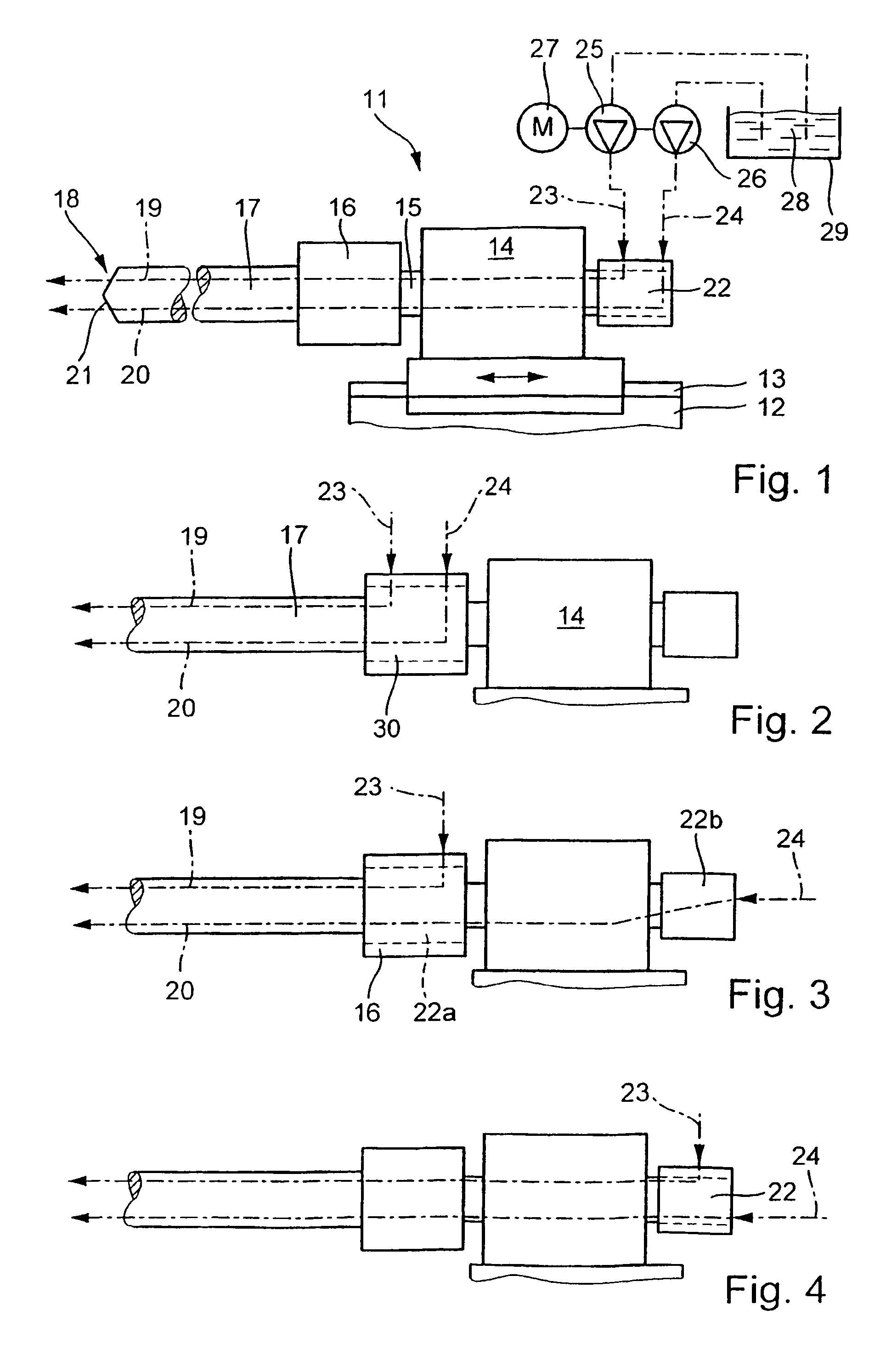
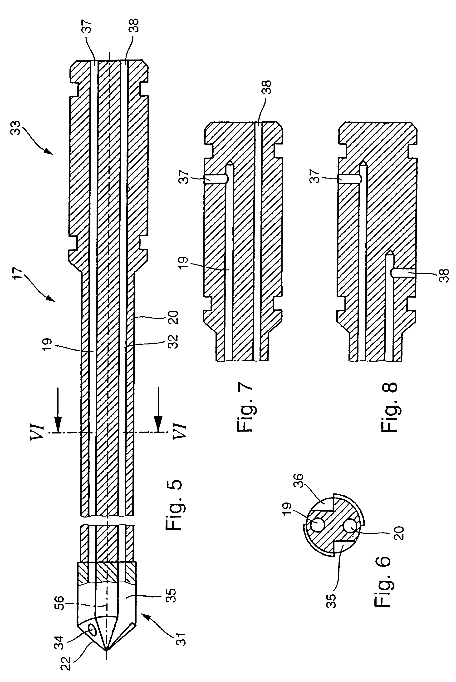
[0027]FIG. 1 shows a drilling device 11 with a machine frame 12 on which a headstock 14 is horizontally displaceable on a carriage 13 and is guided in infeed manner corresponding to the drilling advance. A drilling spindle 15 is mounted in rotary and drivable manner in the headstock 14. On one side of the drilling spindle a drilling tool 17, e.g. a deep drilling tool is clamped in a chuck 16. In the manner described hereinafter, said tool has two cooling lubricant supply channels 19, 20 running longitudinally up to its cutting zone 18 at the free end and which issue into the drilling tool end face 21 forming said cutting zone.

[0028]At the end of the drilling spindle 15 opposite to the drilling tool is provided a rotary duct 22 receiving cooling lubricant for the hole or bore by means of two separate supply lines 23, 24. The latter are supplied by two separate pumps 25, 26 or two pump chambers of the same pump, which can be driven by a common motor 27. They draw the cooling lubricant...


PUM

PropertyMeasurementUnit
angleaaaaaaaaaa
angleaaaaaaaaaa
lengthaaaaaaaaaa

Abstract

The invention relates to a multi-bladed deep drilling tool (17) comprising a cooling lubricant channel (19, 20) provided for each chip space (74) allocated to each cutter (71). Said channels (19,20) are supplied with a lubricant independently from each other, by means of either jointly drives or separately drives lubricating pumps (25, 26). Said channels being associated with either the drilling devise (11) or integrated into an adapter (30) which is pivoted with a common flow of lubricant, but which supplies independent individual flows. Lubrication of the individual cutting zones is guaranteed even if the chip removal channel is blocked, by chips for example. The pressure of the cooling lubricant channel increases in said area whereupon the channel in question is cleared.

Description

FIELD OF APPLICATION AND PRIOR ART[0001]The invention relates to a drilling device with a multiblade drilling tool, particularly a deep drilling tool, having at least two supply channels by means of which cooling lubricant is supplied to the cutting zone.[0002]In addition to the frequently used single-flute deep drilling tools, use is also made of multiblade deep drilling tools, together with other drilling tools such as e.g. twist drills. In the case of heavy duty drills, particularly deep drilling tools, the cutting zone is supplied with cooling lubricant along penetrating channels via the drill and this serves to cool said cutting zone, lubricate guide sections of the drill located in the hole and in particular remove the chips arising during drilling. For this purpose chip removal channels are provided in the drill, e.g. in the form of an axially directed recess (mainly in the case of deep drilling tools) or helical channels in the case of so-called twist drills.[0003]Whereas in...

Claims


Application Information

Patent Timeline
Patent Type & Authority Patents(United States)
IPC IPC(8): B23B51/06B23B51/00B23Q1/00B23Q11/10
CPCB23B51/00B23Q11/1015B23B2251/14Y10T407/14Y10T408/909Y10T408/455Y10T408/44
Inventor TOPF, ERNST
Owner TBT TIEFBOHRTECHN
Why Eureka
Try Eureka