Guide for transmission device

a transmission device and contact technology, applied in the direction of belts/chains/gears, mechanical instruments, belts/chains/gears, etc., can solve the problems of increased manufacturing costs, increased cost of tensioner levers b>500/b>, and difficulty in increasing the thickness of the lever's shoe support base, etc., to achieve high strength, high accuracy of outer dimensions, and reliable molding

Inactive Publication Date: 2009-01-13
TSUBAKIMOTO CHAIN CO
View PDF18 Cites 21 Cited by
  • Summary
  • Abstract
  • Description
  • Claims
  • Application Information

AI Technical Summary

Benefits of technology

[0009]The guide in accordance with the invention comprises a shoe-supporting base adapted for mounting on an engine block and an elongated shoe having a sliding contact surface for sliding engagement with an endless, traveling transmission chain. The shoe is connected to, and supported by, the shoe-supporting base, and has at least one side wall extending from its sliding contact surface in a direction such that it can engage a side of a chain traveling on the sliding contact surface and thereby limit snaking travel of the chain. The shoe also has at least one hook securing the shoe to the shoe-supporting base. The guide is characterized by the fact that the shoe is a sandwich-molded resin structure, having an internal core and a skin layer, the internal core being composed of a resin having a higher strength than the resin of the skin layer, and by the fact that the side wall and hook are both unitary with the skin layer.
[0012]When glass fiber-reinforced polyamide resin is used as the core of the shoe, the strength of the guide is remarkably improved, and the shoe is able to withstand the high loads imposed as a result of increased engine displacement. The polyamide resin forming the skin layer envelops the glass fiber-reinforced core completely, ensures that the guide will retain its shape, and exposes a surface on which the timing chain can slide with low friction, and with minimal wear.

Problems solved by technology

However, in most cases, because of limitations in the space available for the tensioner lever and adjacent engine parts, it is difficult to increase the thickness of the lever's shoe support base.
However the adoption of a higher strength material for the shoe support base results in higher manufacturing costs both because of the increased cost of material, and because of the increased difficulty of molding the higher strength material.
However, the cost of the tensioner lever 500 is increased because of the high cost of the material of the shoe 510.
Moreover, the hooks provided on the shoe for connecting the shoe to the shoe support 520 become less flexible with the adoption of the higher strength shoe material.
The side walls, which extend outward from the chain-contacting surface of the shoe to limit lateral movement of the chain, also become less flexible, and impair the overall flexibility of the shoe.
Consequently, assembly of the tensioner lever becomes more difficult, and cracks, splits, fissures and the like can form in the shoe, making failure due to shoe breakage more likely.

Method used


Image

  • Guide for transmission device
  • Guide for transmission device
  • Guide for transmission device

Examples


Embodiment Construction

[0019]The guide according to the invention will be described with reference to a movable guide, which cooperates with a tensioner to control tension in a timing chain.

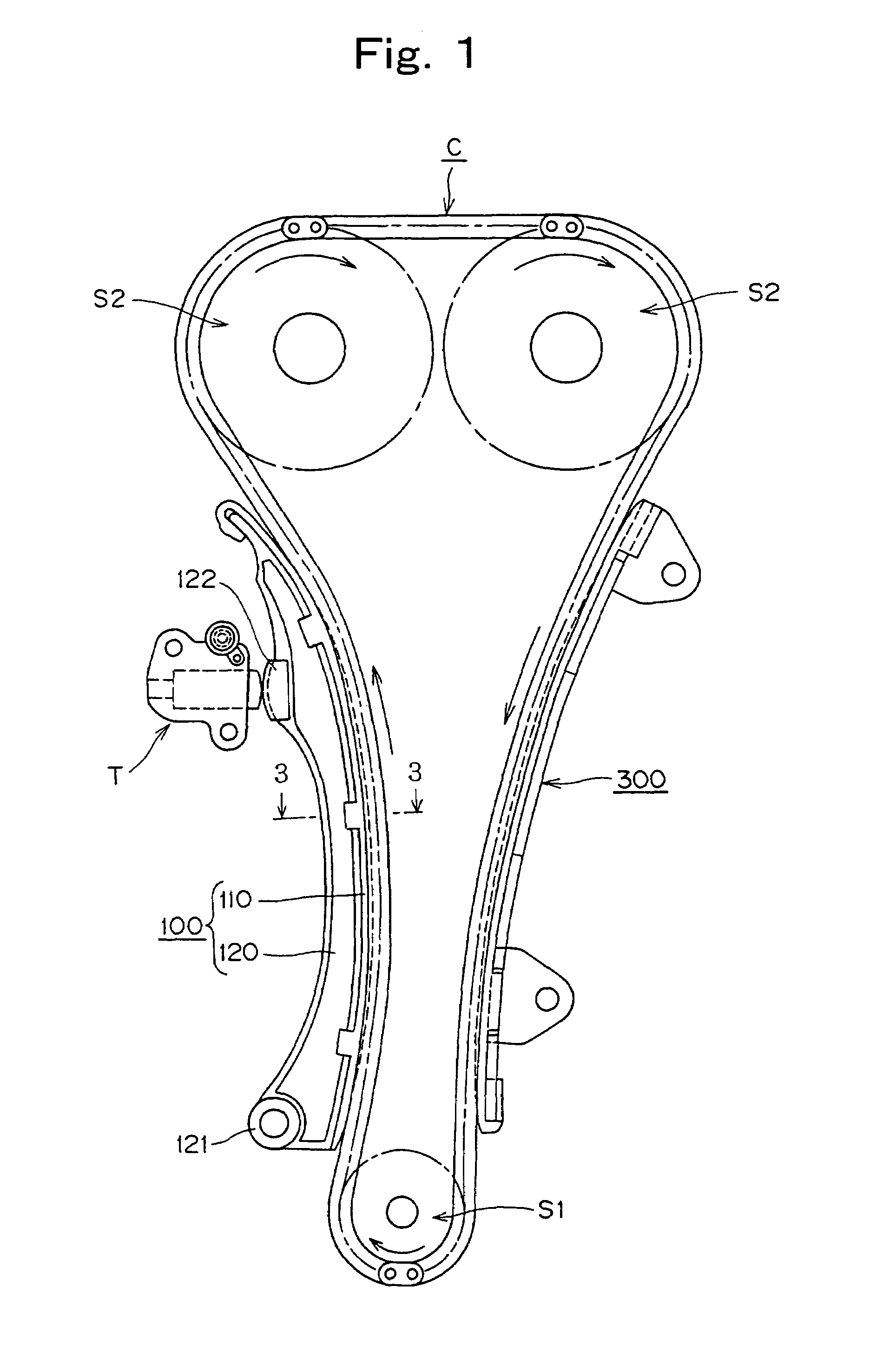
[0020]As shown in FIG. 1, the guide 100 is used in the valve timing system of an internal combustion engine, in which an endless, flexible, timing chain C is driven by a crankshaft sprocket S1, and drives a pair camshaft sprockets S2. The chain is in sliding contact with the shoe 110 of a movable guide 100.

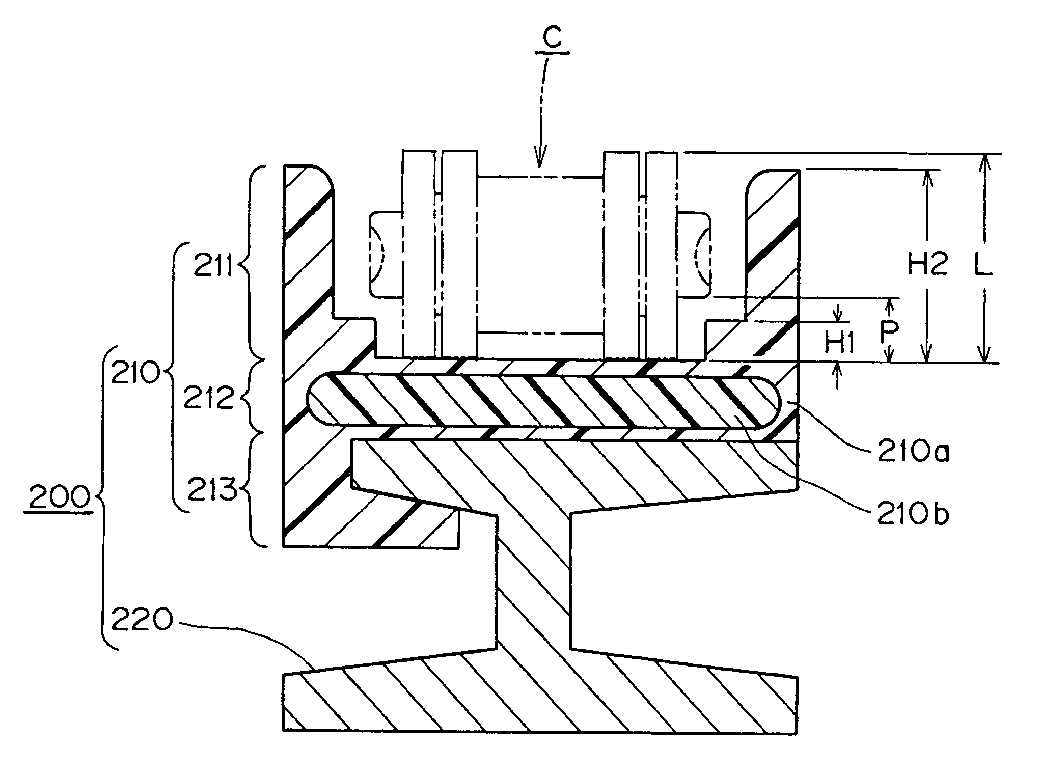
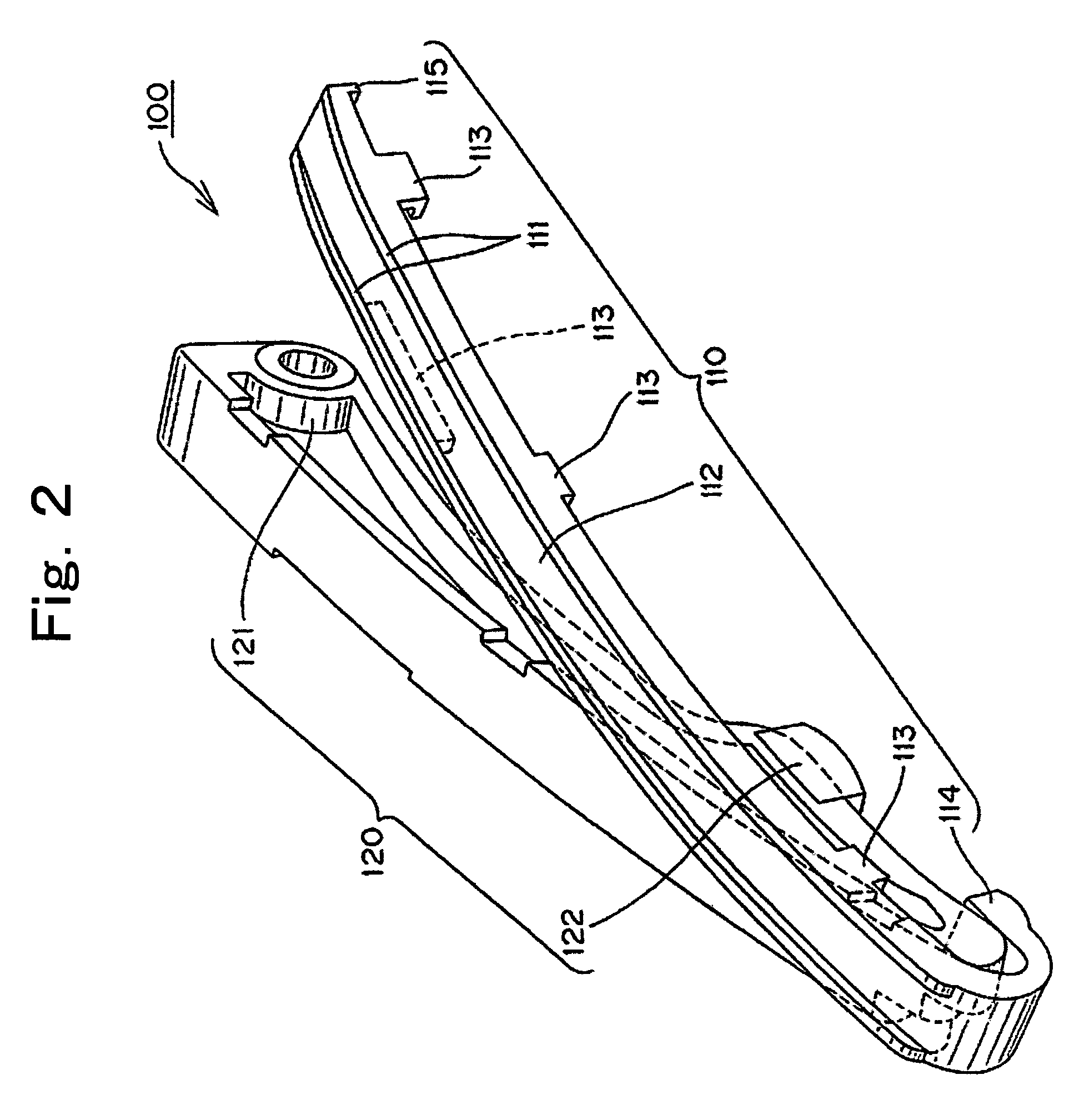
[0021]As shown in FIGS. 1 and 2, the shoe 110 has a substantially arc-shaped surface for sliding contact with the timing chain C, and is held by a supporting base 120 disposed on the back side of the shoe, i.e., the side opposite from the side which is in sliding contact with the chain. A boss 121, having a mounting hole, is provided at one end of the supporting base for receiving a pin or shaft (not shown) on which the guide is pivoted, the pin or shaft being fixed to an engine block. A pad 122 on the back side of t...


PUM


Abstract

A guide for an engine timing chain comprises a metal supporting base and a resin shoe, the shoe having integrally formed hooks for attachment to the supporting base, and integrally formed side walls for limiting lateral movement of the chain on the sliding contact surface of the shoe. A central portion of the shoe has a sandwich injection molded structure and comprises a high strength core of glass fiber-reinforced polyamide resin, and a polyamide skin layer. The side walls and the hooks are formed entirely of the skin layer material.

Description

CROSS REFERENCE TO RELATED APPLICATION[0001]This application claims priority on the basis of Japanese patent application 2005-011608, the disclosure of which is hereby incorporated by reference.FIELD OF THE INVENTION[0002]The invention relates to improvements in a sliding contact guide for an endless, flexible, traveling transmission medium, such as a timing chain for transmitting power from a crankshaft sprocket to one or more camshaft sprockets in an internal combustion engine. The invention is applicable to fixed guides, as well as to movable guides which cooperate with a tensioner to control tension in a transmission medium.BACKGROUND OF THE INVENTION[0003]Japanese Patent Publication No. 3448122 describes a guide of the type to which this invention relates. More particularly, it describes a guide in the form of a tensioner lever composed of a polyamide resin shoe attached to a support base composed of die cast aluminum or glass fiber-reinforced polyamide resin.[0004]In internal ...

Claims


Application Information

Patent Timeline
Patent Type & Authority Patents(United States)
IPC IPC(8): F16H7/18
CPCF16H7/18F16H2007/0872
Inventor KONNO, MASAHIKO
Owner TSUBAKIMOTO CHAIN CO
Why Eureka
Try Eureka