Al technical title is built by PatSnap Al team. It summarizes the technical point description of the patent document.
a technology of tools and methods, applied in the field of tools and procedures, to achieve the effect of reducing fractures, compacting the tissue, and small diameter
Inactive Publication Date: 2009-01-13
SYNTHES USA
View PDF141 Cites 220 Cited by
Summary
Abstract
Description
Claims
Application Information
AI Technical Summary
This helps you quickly interpret patents by identifying the three key elements:
Problems solved by technology
Method used
Benefits of technology
[0034]In another embodiment, deployment of the flapper is controlled such that the flapper has little, if any, range of motion when the flapper is in any position. Thus, in this embodiment, partially turning the collar of the tamp results in partially extending the flapper out of alignment with the tamp body with little, if any, range of motion available to the flapper in any given position. This embodiment provides an advantage of allowing the physician to partially extend the flapper to create a cavity of a smaller diameter than when the flapper is fully extended. When the flapper is to be partially extended in order to gradually create the cavity, it is preferred that a locking or braking device as described above is used to help prevent the flapper from moving out of its desired position.
[0035]While the flapper may be configured and adapted to cut the cancellous tissue, compact or tamp it, or both, in one preferred embodiment the flapper has a blunt tip that primarily compacts the tissue. The blunt tip also may be used to effect reduction of a fracture. In vertebroplasty, for example, the physician may use the blunt tip to perforate the front surface of the vertebrae in order to effect a reduction. In addition, the physician may use the tip to move or reposition the endplate or other bony fragment to help restore the bone to its natural anatomy.
[0036]The flapper also may be curved or may have curved edges to further promote tamping back cancellous tissue when the tamp is rotated. In some applications, cutting may
Problems solved by technology
Moreover, many of the tools described herein may
Method used
Image
Click on the blue label to locate the original text in one second.
Reading with bidirectional positioning of images and text.
Examples
Embodiment Construction
[0083]The present invention is directed to tools and methods for creating cavities in bone. The creation of cavities in bone may be beneficial when bone filler material is to be introduced to the interior of the bone. One advantage is that the creation of a cavity may be used to restrict, contain, or control the delivery of the bone filler material. Another advantage is that the cavity enables the flow and placement of filler material to a desired region.
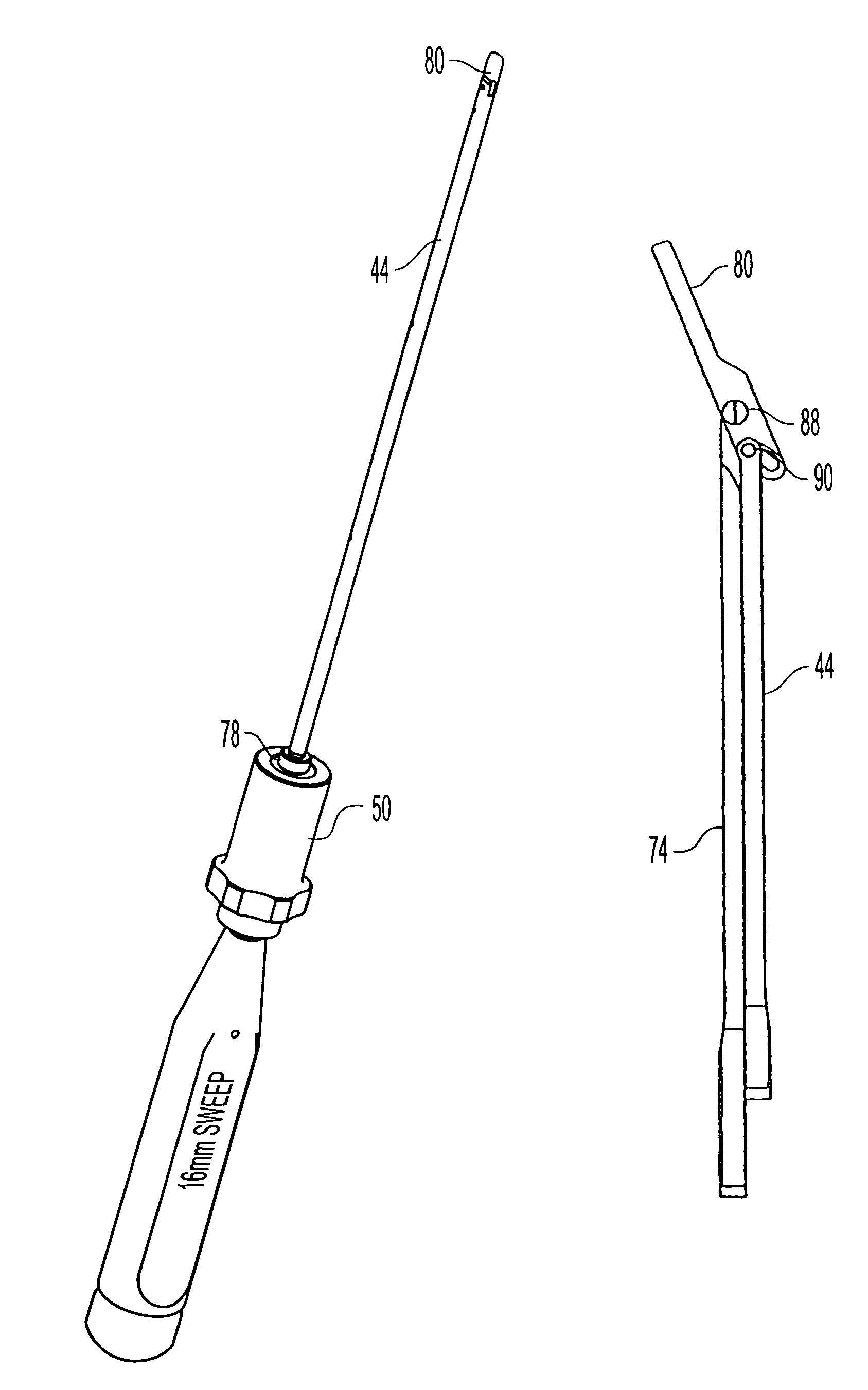
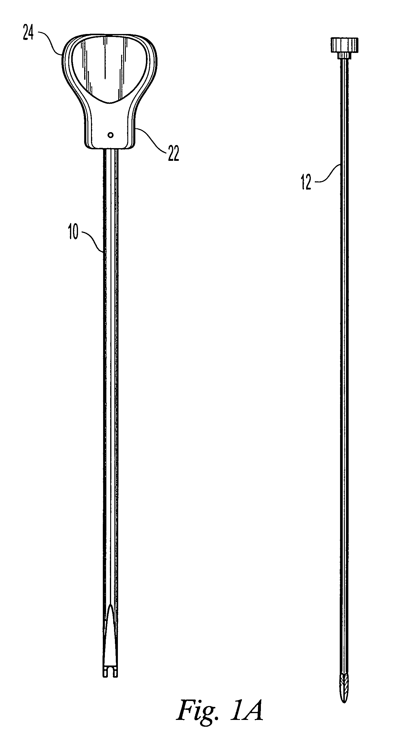
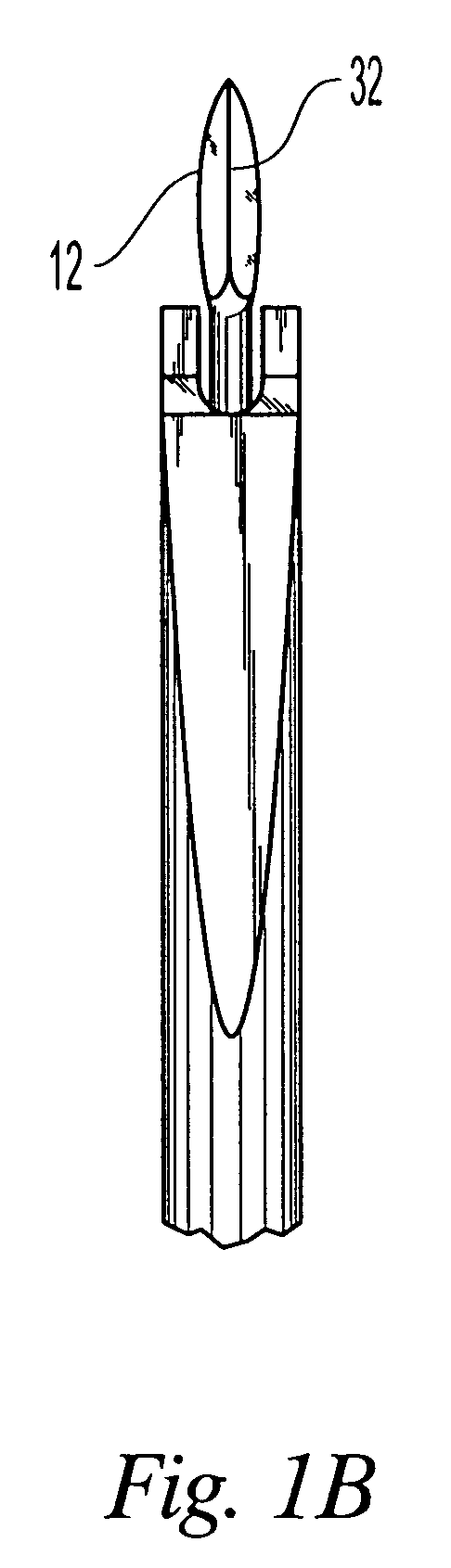
[0084]A combination of the tools described herein may be provided to a physician as a cavity creation system. In one embodiment, the combination of tools are provided in kits according to stages of the procedure in which the tools will be used. For instance, one combination of tools may be selected for a cavity creation approach kit. The cavity creation kit may include, for example, probes, cannulas, and displacement rods. These tools, which are described in greater detail below, can be used to provide access to the treated area.
[00...
PUM
Abstract
Tools for use in the creation of cavities in bones. The tools include a probe, a cannula that provides percutaneous passageway to the interior of the treated bone, a bone tamp, and a system for delivering bone filler material into the cavity. The bone tamp has a shaft that is inserted into the bone through the cannula. The end of the shaft that is inserted into the bone may have a flapper tip that extends out of axial alignment with the shaft upon deployment by the physician. Once the tip is deployed, the bone tamp can be rotated to form the cavity. The cavity may then be treated with a medicament, filled with bone filler material, or both. Other tools and materials described herein may be used to lift or restore the treated bone closer to its natural anatomy.
Description
CROSS-REFERENCE TO RELATED APPLICATIONS[0001]This is a continuation of U.S. patent application Ser. No. 09 / 939,759, filed Aug. 28, 2001 now U.S. Pat. No. 6,679,886, which claims the benefit under 35 U.S.C. § 119(e) of Provisional Application No. 60 / 229,303, filed Sep. 1, 2000.FIELD OF THE INVENTION[0002]The invention relates to tools and procedures, which, in use, form cavities in interior body regions of bones, particularly in vertebrae, for diagnostic or therapeutic purposes.BACKGROUND OF THE INVENTION[0003]Certain diagnostic or therapeutic procedures require the formation of a cavity in a bone mass. This procedure can be used to treat any bone, for example, bone which due to osteoporosis, avascular necrosis, cancer, or trauma, is fractured or is prone to compression fracture or collapse. These conditions, if not successfully treated, can result in deformities, chronic complications, and an overall adverse impact upon the quality of life.[0004]For example, as described in U.S. Pat...
Claims
Application Information
Patent Timeline
Application Date:The date an application was filed.
Publication Date:The date a patent or application was officially published.
First Publication Date:The earliest publication date of a patent with the same application number.
Issue Date:Publication date of the patent grant document.
PCT Entry Date:The Entry date of PCT National Phase.
Estimated Expiry Date:The statutory expiry date of a patent right according to the Patent Law, and it is the longest term of protection that the patent right can achieve without the termination of the patent right due to other reasons(Term extension factor has been taken into account ).
Invalid Date:Actual expiry date is based on effective date or publication date of legal transaction data of invalid patent.