Method and apparatus for a chip-level no-decision feedback equalizer for CDMA wireless systems

a wireless system and nodecision feedback technology, applied in the field of method and apparatus for a nodecision feedback equalizer for cdma wireless systems, can solve the problems of electrical power consumption, large area of integrated electronic circuits, etc., and achieve the effects of saving resources on handset receivers, reducing complexity, and reducing the number of transistors

Inactive Publication Date: 2009-01-13
ADVANCED RECEIVER TECH
View PDF5 Cites 32 Cited by
  • Summary
  • Abstract
  • Description
  • Claims
  • Application Information

AI Technical Summary

Benefits of technology

[0012]One problem with the use of prior art complex CDMA receiver designs is that they consume more resources, both in terms of area on an integrated electronic circuit and in terms of electrical power. Although these resources may not be scarce for base station receiver applications, they are for handset receiver applications. The invention is directed generally to a 3 G CDMA receiver design that has a performance comparable to the better complex receiver designs, e.g., the iterative chip-level DFE, while retaining a complexity that is comparable to or less than a conventional rake receiver, thus conserving resources on a handset receiver.
[0013]According to a preferred embodiment for such a 3 G CDMA receiver, a chip-level, no-decision feedback equalizer (NDFE) provides a basis for a low complexity, high performance receiver for 3 G CDMA signals. Chip-level decisions are avoided as they are simply not readily available given the 3 G CDMA signals that are designed to be loaded with multiuser data-channels by means of orthogonal short codes, e.g., the OVSF codes of W-CDMA. The NDFE employs the output of the differential combiner of the feedforward filter output and the feedback filter outpu

Problems solved by technology

One problem with the use of prior art complex CDMA receiver designs is that they consume more reso

Method used


Image

  • Method and apparatus for a chip-level no-decision feedback equalizer for CDMA wireless systems
  • Method and apparatus for a chip-level no-decision feedback equalizer for CDMA wireless systems
  • Method and apparatus for a chip-level no-decision feedback equalizer for CDMA wireless systems

Examples


Embodiment Construction

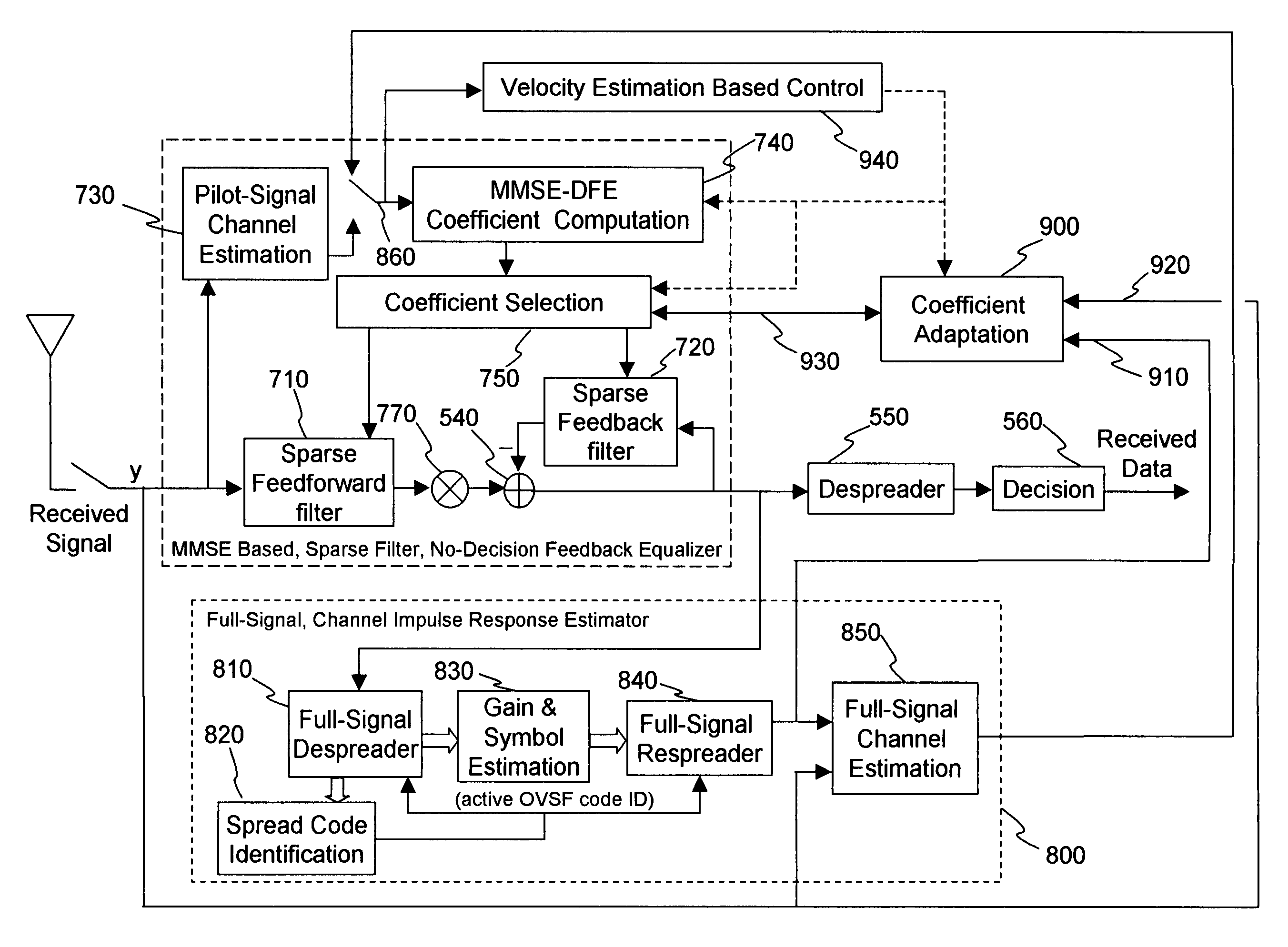
[0027]FIG. 5 shows a block diagram of certain processes performed by a system implementing a chip-level no-decision feedback equalizer (NDFE) 500 in a CDMA receiver. The performance of the chip-level NDFE receiver for the 3 G CDMA downlink signals is such that a handset application requires only a single antenna 510. The received signal is optimally sampled at the chip-rate to form the input y to the feedforward filter 520. The chip rate outputs of the feedforward filter 520 and the feedback filter 530, y_FF and y_FB, respectively, are differentially combined by summation element 540 to form the NDFE output, z=y_FF−y_FB. Note that the differential combiner output z is directly fed back as input to the feedback filter 530, without an intervening non-linear decision element. The feedforward filter, feedback filter and differential combiner form the NDFE that is identified in FIG. 5 and that is structurally an IIR linear filter with input y and output z. The NDFE output z is input to a...


PUM


Abstract

A method and apparatus for constructing a model of a sampled transmitted CDMA downlink signal comprises receiving a sampled signal at a first module (810), wherein the signal received at the first module has been filtered, receiving despread symbol data for all possible spread codes at a second module (820) from the first module, determining active codes of the possible spread codes in the filtered sampled signal by the second module, receiving from the first module, the despread symbol data identified with the active codes, at a third module (830), providing estimates of a symbol value and a gain based on the symbol data identified with the active codes by the third module, receiving the symbol value and gain estimates from the third module and the active codes from the second module at a fourth module (840), and constructing a model of the sampled transmitted CDMA downlink signal using the symbol value and gain estimates for the active codes by the fourth module.

Description

CROSS-REFERENCE TO RELATED APPLICATIONS[0001]The present patent application is related to and claims the benefit of provisional patent application Ser. No. 60 / 651,716, filed on Feb. 10, 2005, entitled Method And Apparatus For A Chip-Level No-Decision Feedback Equalizer For CDMA Wireless Systems. Further, the present patent application is a Continuation-In-Part of patent application Ser. No. 11 / 280,858, filed on Nov. 16, 2005, entitled Chip-Level No-Decision Feedback Equalizer For CDMA Wireless Systems. Still further, the present application is related to patent application Ser. No. 10 / 796,596 filed on Mar. 9, 2004, entitled Methods and Apparatus For Single Burst Equalization of Single Carrier Signals In Broadband Wireless Access Systems, the entire contents of each of which are enclosed by reference herein.BACKGROUND OF INVENTION[0002]The Third Generation Partnership Project (3GPP) organization develops the world-harmonized specifications for mobile, multimedia, wireless cellular co...

Claims


Application Information

Patent Timeline
IPC IPC(8): H04B7/216
CPCH04B1/7103H04L25/0212H04L25/0232H04L25/03057H04L2025/0349H04L2025/03605
Inventor MCKOWN, RUSSELL
Owner ADVANCED RECEIVER TECH
Why Eureka
Try Eureka