Method of manufacturing a device with a cavity
a manufacturing method and micro-device technology, applied in micro-structural devices, electrostatic generators/motors, generators/motors, etc., can solve the problems of air gaps between metal lines and large dielectric areas, methods that are less compatible with back-end-of-line (beol) processing, and achieve the effect of more beol-processing compatibility
- Summary
- Abstract
- Description
- Claims
- Application Information
AI Technical Summary
Benefits of technology
Problems solved by technology
Method used
Image
Examples
first embodiment
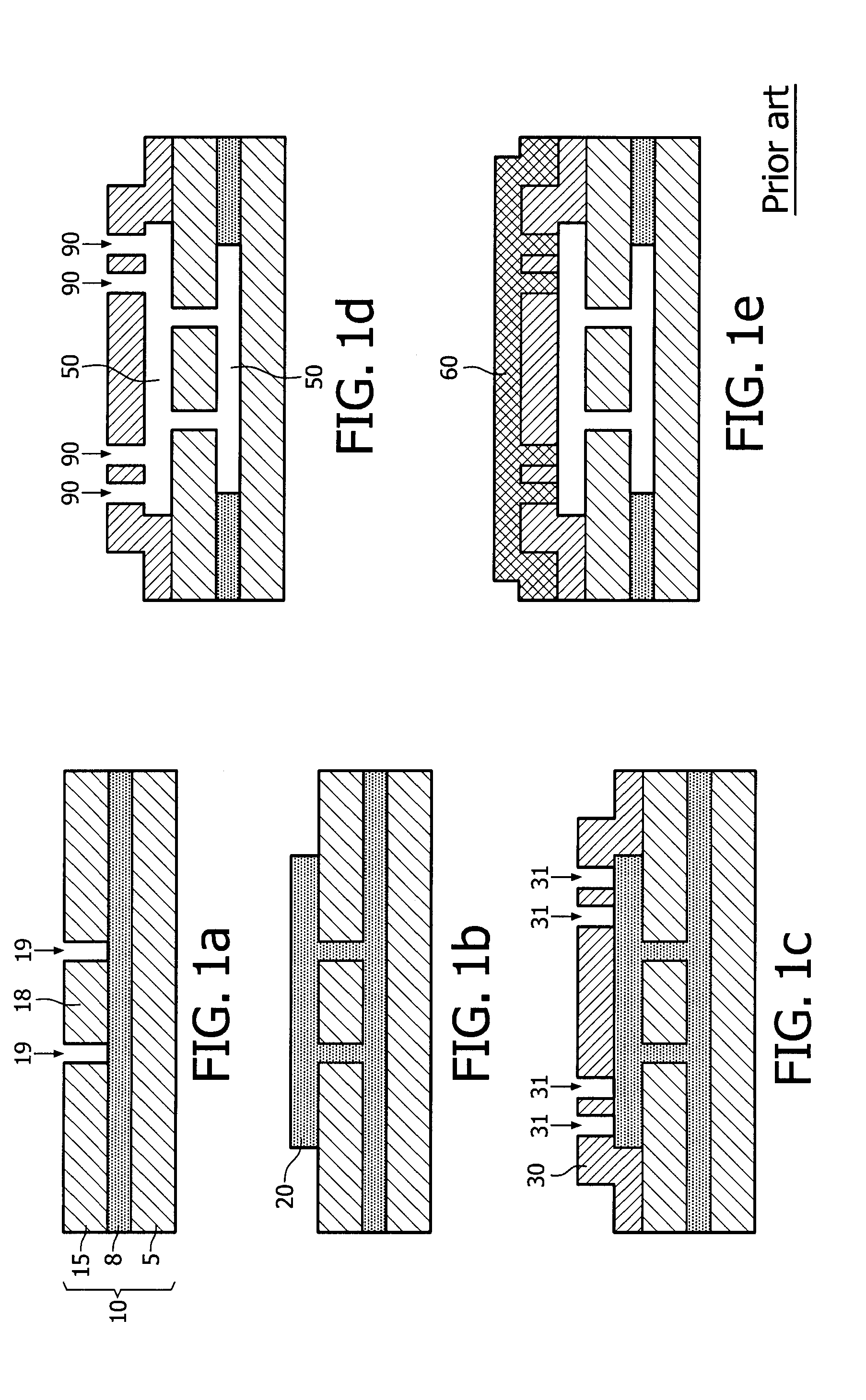
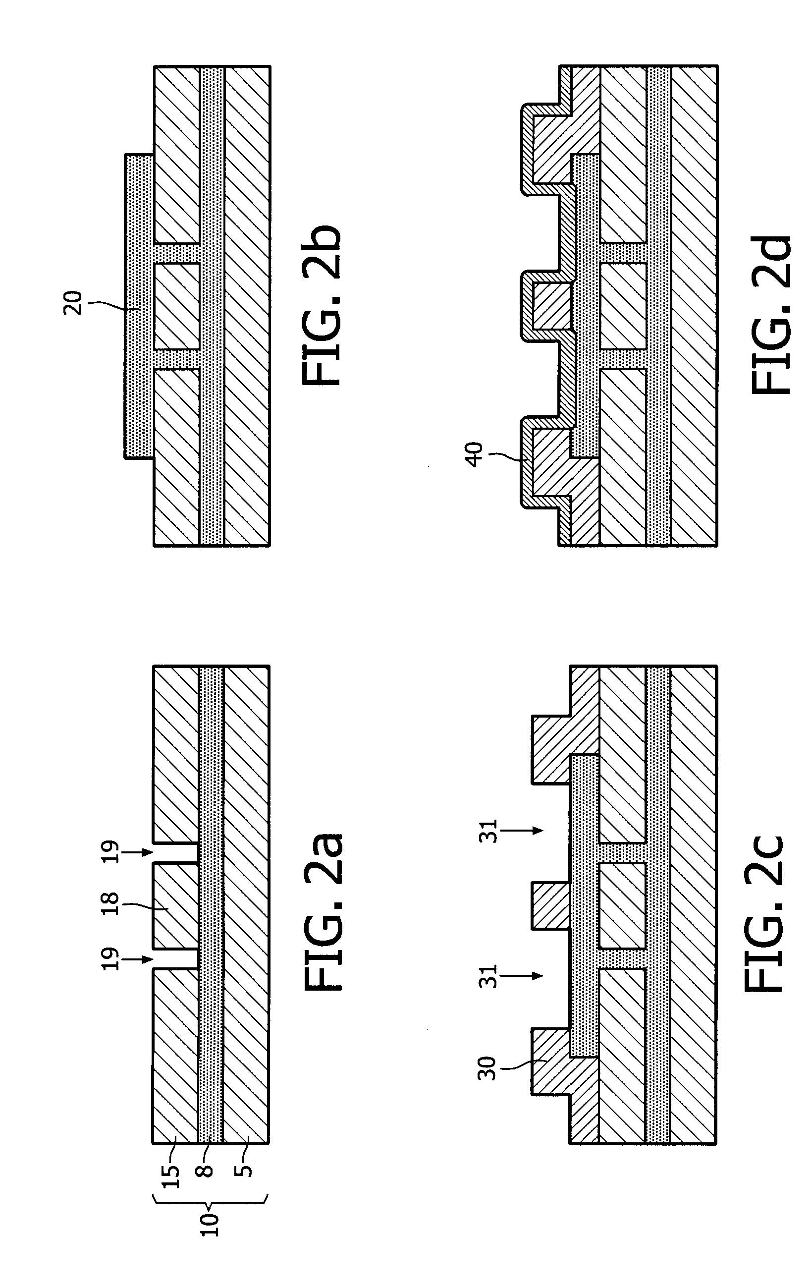
[0072]FIGS. 2a to 2f schematically show an encapsulation process of a MEMS device in accordance with the method of the invention. This process will be discussed in as far as it differs from the known process illustrated in FIGS. 1a to 1e. The first two steps (FIGS. 2a and 2b) are the same as the first two steps of the known process. The third step, illustrated in FIG. 2c differs from the third step of the known method in that the release holes 31′ in the packaging cap layer 30 may be designed much larger and may also be located above the moveable component 18. In the step of FIG. 2a, if the sacrificial oxide layer 8 is not an oxide it has to be removed before the sacrificial oxide layer 20 is deposited, because it will have to be removed together with the sacrificial oxide layer 20.
[0073]The step of FIG. 2d is new. In this step a porous layer 40 is deposited on the packaging cap layer 30 and in the release holes. The inventors have discovered that the material of the porous layer 40...
second embodiment
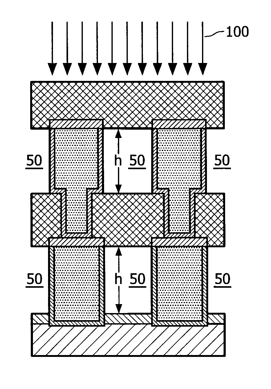
[0084]FIGS. 6a1 and 6a2 schematically show an etching step carried out between two process stages of a first experiment proving the feasibility of the method of the invention. FIGS. 6b to 6d show cross-section SEM pictures of devices in accordance with FIG. 6a2 for different porous layer thicknesses, 700 nm, 500 nm, and 300 nm, respectively. In FIG. 6a1 the porous layer 30 is directly used as packaging cap layer. The most important result of this second experiment is that even a 700 nm thick BD layer was porous enough to remove the sacrificial (oxide) layer 20 as is visible in FIG. 6b. The BD layer must be chosen thick enough to withstand the deposition of a sealing layer 60 (FIG. 5), which also depends on the sealing requirements.
third embodiment
[0085]FIGS. 7a to 7j show different stages in a method of manufacturing a semiconductor device in accordance with the method of the invention.
[0086]In the step of FIG. 7a a substrate 110 is provided comprising a semiconductor body 105. The semiconductor body 105 may comprise any one of the following semiconductor materials and compositions like silicon (Si), germanium (Ge), silicon germanium (SiGe), gallium-arsenide (GaAs) and other III-V compounds like indium-phosphide (InP), cadmium sulfide (CdS) and other II-VI compounds, or combinations of these materials and compositions. The semiconductor body may comprise active elements like transistors and diodes (not shown). These active elements together may form an electronic circuit (not shown). In any case, connection of the active elements is done via interconnect layers. These interconnect layers have parasitic capacitances which are defined by the dielectric constant of surrounding materials. The semiconductor body may even comprise...
PUM
| Property | Measurement | Unit |
|---|---|---|
| thickness | aaaaa | aaaaa |
| dielectric constant | aaaaa | aaaaa |
| temperature | aaaaa | aaaaa |
Abstract
Description
Claims
Application Information
 - R&D
- Intellectual Property
- Life Sciences
- Materials
- Tech Scout
- Unparalleled Data Quality
- Higher Quality Content
- 60% Fewer Hallucinations
Browse by: Latest US Patents, China's latest patents, Technical Efficacy Thesaurus, Application Domain, Technology Topic, Popular Technical Reports.
© 2025 PatSnap. All rights reserved.Legal|Privacy policy|Modern Slavery Act Transparency Statement|Sitemap|About US| Contact US: help@patsnap.com


