Method for counteracting the occlusion effects

a technology of occlusion and effect, applied in the direction of instruments, electrical equipment, sound producing devices, etc., can solve the problems of sound pressure build-up in the cavity, and achieve the effect of reducing or eliminating the low frequency sound built-up

Active Publication Date: 2009-01-13
OTICON
View PDF9 Cites 40 Cited by
  • Summary
  • Abstract
  • Description
  • Claims
  • Application Information

AI Technical Summary

Benefits of technology

[0005]This is achieved in a method for counteracting the occlusion effect of an electronic device delivering an audio signal to the ear, like a hearing aid or an active ear protector. The electronic device includes a transmission path with an external microphone or input line which receives a signal from the environment and a signal processor and a receiver which receives a signal from the signal processor and delivers sound signals to the ear, whereby an ear piece is inserted into the ear canal and totally or partially blocks the canal. The sound conditions in the cavity between the ear piece and the tympanic membrane are directly or indirectly determined, and whenever conditions leading to occlusion problems are present, the transmission characteristic of the transmission path to the receiver counteracts the occlusion effect.
[0007]In an embodiment of the invention the conditions leading to occlusion problems are determined by monitoring the activity of the user's own voice, and when a user's own voice activity is detected, the amplification through the signal processor in the frequency region below 1 kHz is reduced. It is the sound transmission through the tissue of the sound from a user's own voice which often leads to the sound pressure build up in the cavity. This can be compensated for by reducing the amplification through the hearing aid in the relevant frequency region below 1 kHz. Hereby, the total sound pressure level in the cavity becomes comfortable. There are a number of ways in which a user's own voice activity can be monitored. One way is to analyze the input signal from the usual microphone and to determine when characteristics which are special to the user's voice are present in the signal. Also, it is possible to use a vibration monitor which monitors the level of vibration in the tissue adjacent to the ear piece. Possibly, the vibration monitor is built into the ear piece.
[0009]When the occlusion problem is solved as described above the attenuation of the low frequency parts of the sound also is applied to the sound, which is received from the surroundings, and this is not desirable. This can be overcome by having the signal processor amplify the low frequency part of the signal from the external microphone in order to compensate for the attenuation of the useful part of the signal from the external microphone or input line. In this way the useful low frequency parts of the signal, which are attenuated by the feed back loop, may be restored in the signal processor. Thus, the user gets the sound from the surroundings with the usual amplification while the occlusion effect is removed or reduced.
[0011]In an embodiment of the invention the sound entering the cavity from the tissue and causing the problematic sound levels in the cavity is captured by a viberation pick-up device. The viberation signal is filtered in a filter and combined with the signal which is captured by the external microphone or input line of the device. In this way the cause of the occlusion problem, namely the sound conducted into the ear canal from the surrounding tissue, is used in a direct feed forward manner to eliminate or reduce the low frequency sound built up in the cavity. processor amplify the low frequency part of the signal from the external microphone in order to compensate for the attenuation of the useful part of the signal from the external microphone or input line. In this way the useful low frequency parts of the signal, which are attenuated by the feed back loop, may be restored in the signal processor. Thus the user gets the sound from the surroundings with the usual amplification while the occlusion effect is removed or reduced.
[0013]In an embodiment of the invention the sound entering the cavity from the tissue and causing the problematic sound levels in the cavity is captured by a vibration pick-up device. The vibration signal is filtered in a filter and combined with the signal which is captured by the external microphone or input line of the device. In this way the cause of the occlusion problem, namely the sound conducted into the ear canal from the surrounding tissues is used in a direct feed forward manner to eliminate or reduce the low frequency sound built up in the cavity.
[0014]In a further embodiment of the invention an inward pointing microphone monitors the sound pressure in the cavity. This signal is compared with the signal from the external microphone or input line, and where the comparison result is used to control the shape of the filter. In this way it is assured that the sound inside the ear canal is not allowed to become elevated due to sounds transmission through the tissue of the user and into the ear canal.

Problems solved by technology

It is the sound transmission through the tissue of the sound from a user's own voice which often leads to the sound pressure build up in the cavity.

Method used


Image

  • Method for counteracting the occlusion effects
  • Method for counteracting the occlusion effects
  • Method for counteracting the occlusion effects

Examples


Embodiment Construction

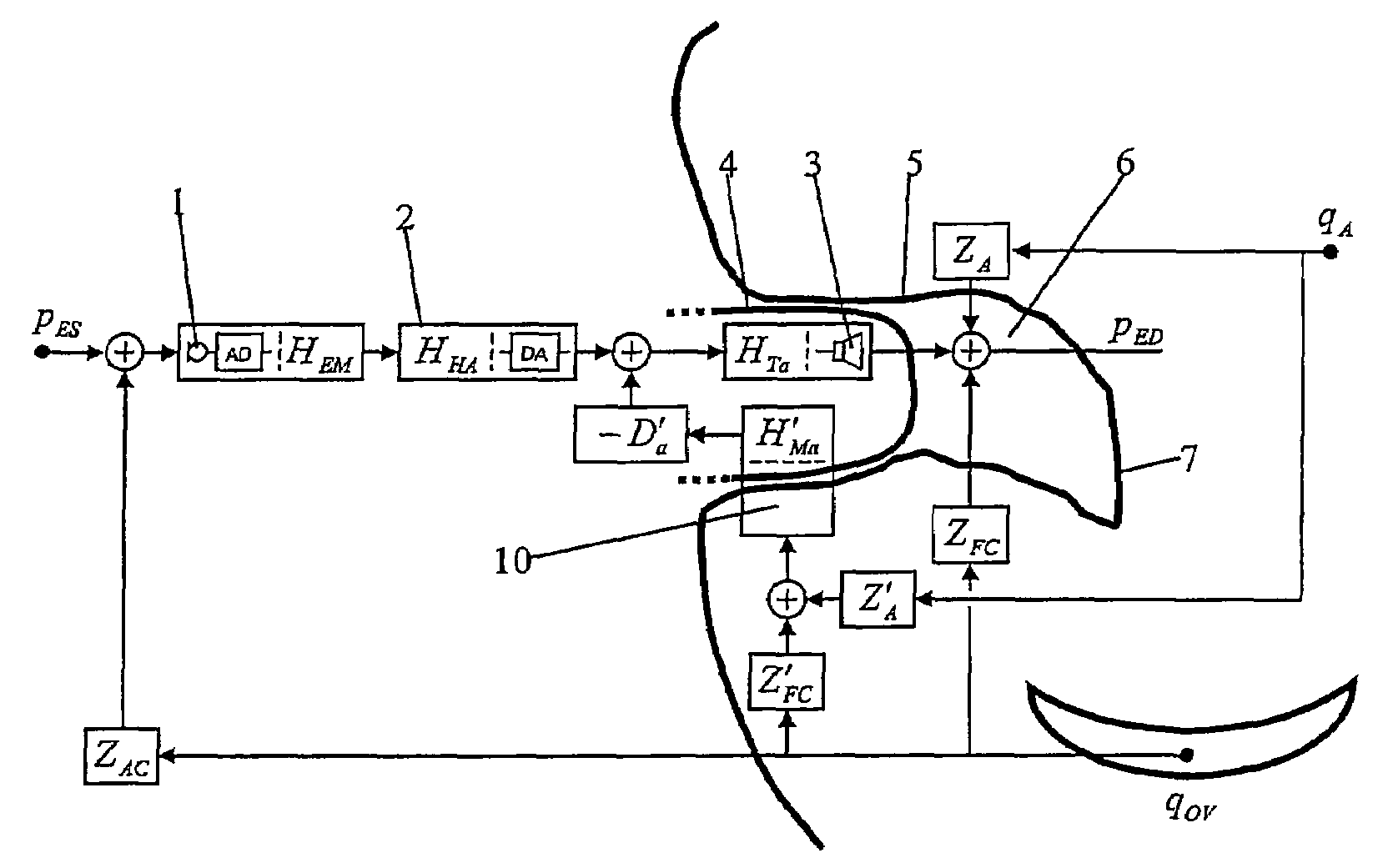
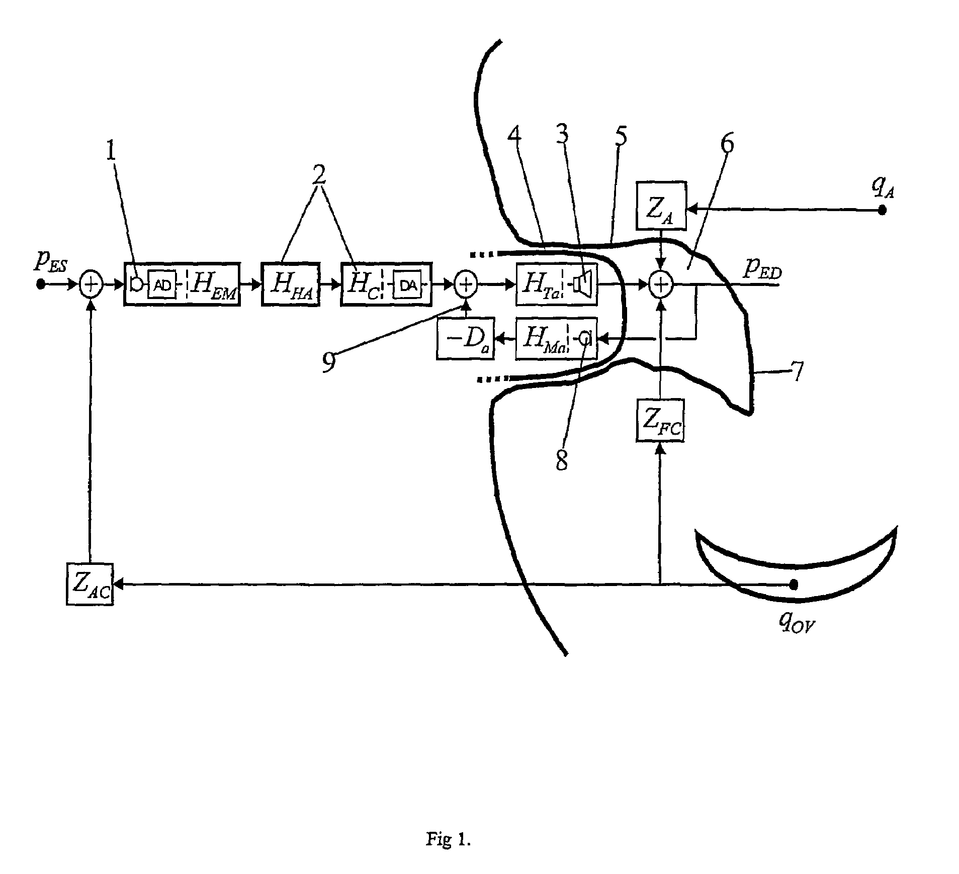
[0018]The system of FIG. 1 comprises a microphone block comprising microphone 1, AD-converter AD and transfer function HEM. The system further comprises block 2 comprising hearing aid block HHA, additional digital block HC and DA-converter DA. An internal microphone 8 is used in a conventional feed back control system as sketched in FIG. 1. Note that the control loop 9 is assumed to be formed in the analog domain. This is reflected in symbols for the receiver 3 HTa and internal microphone 8 HMa, transfer functions, where the subscript a denotes a transfer function between two analog signals. Furthermore, the transfer function of the analog feed back controller is denoted by Da and finally an additional digital block HC has been added after the hearing aid block HHA, as a means of correcting the changes to the amplification characteristic of the hearing aid introduced by the feed back control system. In this set-up HC also includes the conversion from discrete time signal to analogue...


PUM


Abstract

A method for counteracting the occlusion effect of an electronic device delivering an audio signal to the ear, like a hearing aid or an active ear protector, where the electronic device includes a transmission path with an external microphone or input line which receives a signal from the environment and an signal processor and a receiver which receives processes signal from the signal from the signal processor and delivers sound signals to the ear, whereby an ear piece is inserted into the ear canal and totally or partially blocks the canal. The sound conditions in the cavity between the ear piece and the tympanic membrane are directly or indirectly determined, and whenever condition leading to occlusion problems are determined, the transmission characteristics of the transmission path or the receiver changes in order to counteract the occlusion effect.

Description

AREA OF THE INVENTION[0001]This invention relates to a method for counteracting the occlusion effect of a sound protector and / or communication device like a hearing aid, whereby an ear piece is inserted into the ear canal and totally or partially blocks the canal.BACKGROUND OF THE INVENTION[0002]One of the most common complaints of hearing aid users is that their own voice sounds unnatural: boomy, hollow or echoing. Poor sound quality of a person's own voice is also one of the top ten reasons why some hearing aids end up in the drawer. This problem with a person's own voice is very often due to the so-called occlusion effect which occurs because the body-conducted contribution to a person's perception of his / her own voice is trapped in the cavity between the occluding earmold of the hearing instrument and the tympanic membrane. The result is a build-up of sound pressure at low frequencies that may be as much as 30 dB relative to the open-ear. Typically, the occlusion effect has a fl...

Claims


Application Information

Patent Timeline
Patent Type & Authority Patents(United States)
IPC IPC(8): H04R25/00G10K11/16
CPCH04R25/505H04R2460/05A61F2011/145A61F11/145
Inventor RASMUSSEN, KARSTEN BOLAUGESEN, SOREN
Owner OTICON
Why Eureka
Try Eureka