
Method of and system for routing in a photonic network

a photonic network and network routing technology, applied in multiplex communication, optics, instruments, etc., can solve the problems of difficult scaling, unsuitable for providing on-demand services, and still largely pre-planned, and achieve the problem of interoperability between different vendor's equipment and different telecommunications providers

Active Publication Date: 2009-01-13
CIENA
View PDF5 Cites 40 Cited by
  • Summary
  • Abstract
  • Description
  • Claims
  • Application Information

AI Technical Summary

Benefits of technology

[0029]controlling terminating nodes of the one or more optically viable photonic paths of ...

Problems solved by technology

However, telecommunications providers have, in the past, deployed such optical networks after considerable planning through manual processes taking many months.
However, such topologies are still largely pre-planned, difficult to scale and generally unsuitable for providing on-demand services.
Furthermore, interoperability between different vendor's equipment and different telecommunications providers has been problematic.
However, routing in photonic networks must take account of peculiarities of the optical transmission media which are quite unlike electronic transmission media used in conventional electronic IP networks.
Various photonic effects impair the optical signal being transmitted and limit the maximum reach of the optical transmission media.
When an optical signal is routed through multiple consecutive PSs, the signal impairment accumulates.
There comes a point where the cumulative impairment of the optical signal reaches an unacceptable level in terms of signal quality or bit error rate (BER).
This means that a path computed by a routing algorithm may not be viable because it may contain a path segment through multiple consecutive PSs in which the cumulative photonic effects impair the optical signal at an unacceptable level.
The problem is exacerbated by the fact that these photonic effects depend not only on the static configuration and specifications of the optical transmission media, but also on the dynamic state of existing connections provisioned across the network.
However, this solution requires pre-planning and does not provide many of the advantages of an unplanned network mentioned above, such as scalability and efficiency.
However, as described above, photonic effects are complex and depend on both the static configuration and specifications of the optical transmission media and the dynamic state of connections provisioned across the network.
As a result, such approaches tend to produce over-complex routing algorithms which are computationally intensive, if not intractable.
However, given the above-mentioned complexity, previous work has often ignored this and instead optimised for least optical impairment as this guarantees a viable path if there is one to be found, but also optical impairment generally has some correlation with actual equipment cost.
However, where line systems are mixed (more likely in a larger photonic network), fibre types are mixed, financial arrangements intervene (e.g. rent-on-demand fibres that are much more expensive than operator owned fibres) or for many other reasons, this approximation may break down.
Prior art mechanisms have been produced to perform a dual optimisation between the two factors of cost and optical viability, but these usually have fixed models of both—and often don't deliver a guaranteed optimal cost.

Method used


Image

  • Method of and system for routing in a photonic network
  • Method of and system for routing in a photonic network
  • Method of and system for routing in a photonic network

Examples


Embodiment Construction

[0048]These embodiments represent the best ways of putting the invention into practice that are currently known to the Applicants although they are not the only ways in which this could be achieved.

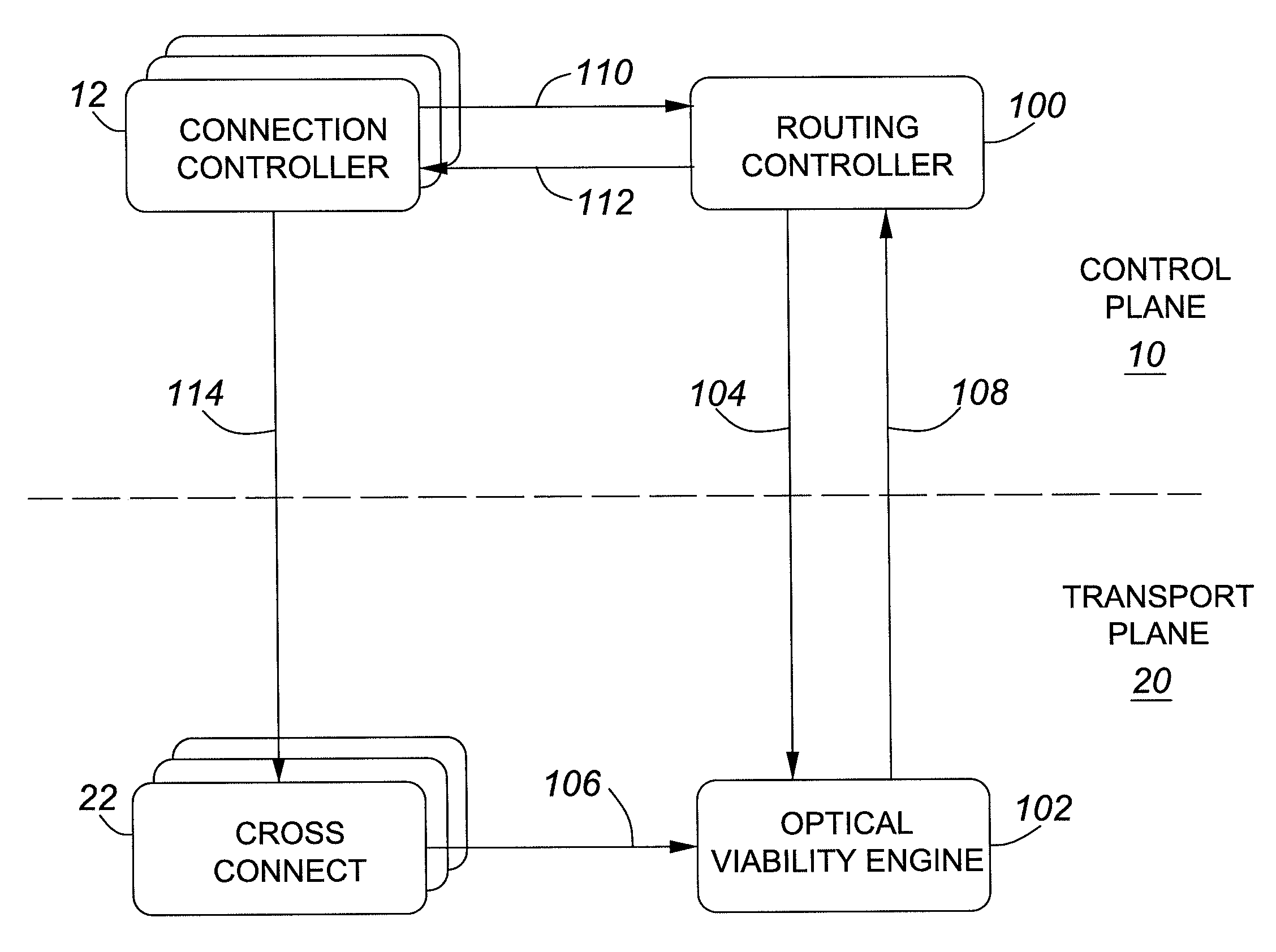
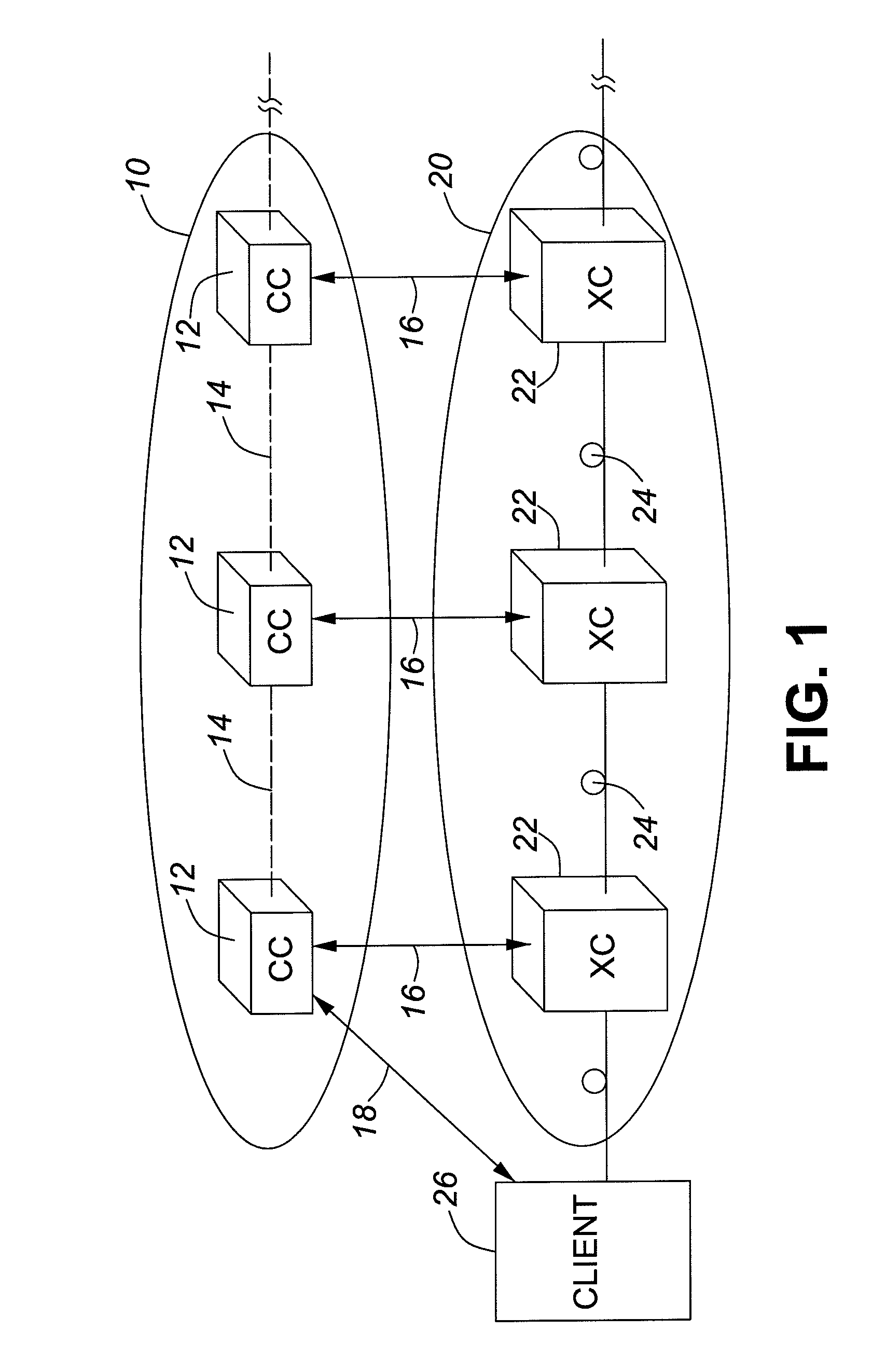
[0049]Control of XCs in a photonic network will be achieved through the introduction of a network control plane ‘above’ the transport plane. Various telecommunications standards bodies are currently working towards defining protocols, architecture and functional requirements of such a control plane.

[0050]Notably, the International Telecommunication Union (ITU-T) has produced architectural and functional recommendations for what is called the Automatically Switched Transport Network (ASTN), also sometimes referred to as the Automatically Switched Optical Network (ASON). The general architectural specification of the ASTN is set out in ITU-T Recommendation G.8080. The recommendations concerning routing architecture and functionality of the ASTN are set out in ITU-T Recommendation G.7715. Th...


PUM


Abstract

A method of and system for determining a path through which to route a connection in a photonic network in which optically viable photonic paths of one or more physical links are determined and considered as “virtual” links in a “virtual” topology. Routing is then performed using the “virtual” topology rather than the physical topology to compute “virtual” paths of one or more “virtual” links.

Description

FIELD OF THE INVENTION[0001]The present invention relates to a method of and a system for selecting a path through which to route a connection in a photonic network.BACKGROUND OF THE INVENTION[0002]Optical networks, such as the Synchronous Optical Network (SONET), Synchronous Digital Hierarchy (SDH) transport networks and Optical Transport Network (OTN) are well known. Through the use of Wavelength Division Multiplexing (WDM) or Dense WDM (DWDM), these optical networks are able to meet the bandwidth and capacity requirements of many new telecommunications services.[0003]However, telecommunications providers have, in the past, deployed such optical networks after considerable planning through manual processes taking many months. Typically, the network architecture would be designed, equipment ordered, installed, tested and then connections provisioned across the network. The use of ring topologies and optical cross connects has brought about the ability to set up end-to-end connectio...

Claims


Application Information

Patent Timeline
IPC IPC(8): H04B10/00H04J14/00
CPCH04Q11/0062H04Q2011/0073H04Q2011/0079H04Q2011/009
Inventor PEETERS, BRAMROBERT, FRISKNEYSHIELDS, JAMES
Owner CIENA
Learn More