Display device with varying phosphor structure

a phosphor structure and display device technology, applied in the field of display devices, can solve the problems of low excitation efficiency, insufficient luminance, low color temperature, etc., and achieve the effects of less variation in emission luminance of each gas discharge tube, high throughput, and variable phosphor layer capacity

Inactive Publication Date: 2009-01-20
SHINODA PLASMA
View PDF26 Cites 2 Cited by
  • Summary
  • Abstract
  • Description
  • Claims
  • Application Information

AI Technical Summary

Benefits of technology

[0012]According to the first aspect of the invention, the phosphor layer is formed inside the gas discharge tube so that the distance (height) between one support body that makes a pair with the other support body on which a plurality of pairs of electrodes extending in a direction crossing the axial direction of the gas discharge tubes are disposed and an end of the phosphor layer on said other support body side varies depending on each emission color. The luminescence intensity and color characteristic of the phosphor layer are determined by the phosphor material used. Therefore, by changing the height of the phosphor layer with respect to the other support body based on the phosphor material used, it is possible to adjust the distance to the discharge region for each emission color and allow the display device to have a desired color temperature (value). More specifically, by increasing the height of the phosphor layer, it is possible to shorten the distance between the facing phosphor layer and one support body that is the discharge region, prevent self-absorption of ultraviolet radiation and increase the utilization efficiency, and it is also possible to increase the amount of phosphor receiving the ultraviolet radiation and consequently increase the luminescence intensity.
[0025]As described above, according to the present invention, in the case where the phosphor layer is formed on a part of the inner surface of the gas discharge tube, the height of the phosphor layer with respect to the rear support body of the gas discharge tubes is varied depending on each emission color, and therefore it is possible to adjust the distance to the discharge region (discharge electrode pair) for each emission color of the phosphor layers and allow the display device to have a desired color temperature. Moreover, according to the present invention, by forming the phosphor layers whose thickness varies depending on each emission color, it is possible to adjust the excitation efficiency for each emission color of the phosphor layers and allow the display device to have a desired color temperature. Furthermore, according to the present invention, by changing the shapes of the electrodes for discharging the discharge gas so that their shapes on the gas discharge tubes including the phosphor layers vary depending on each emission color of the phosphor layers, it is possible to adjust the amount of discharge current for each emission color of the phosphor layers and allow the display device to have a desired color temperature.

Problems solved by technology

By the way, in a display device as described above, a blue phosphor has lower excitation efficiency compared to a green phosphor and a red phosphor, and consequently there is a problem that the blue phosphor has insufficient luminance and causes a low color temperature.

Method used


Image

  • Display device with varying phosphor structure
  • Display device with varying phosphor structure
  • Display device with varying phosphor structure

Examples


embodiment 1

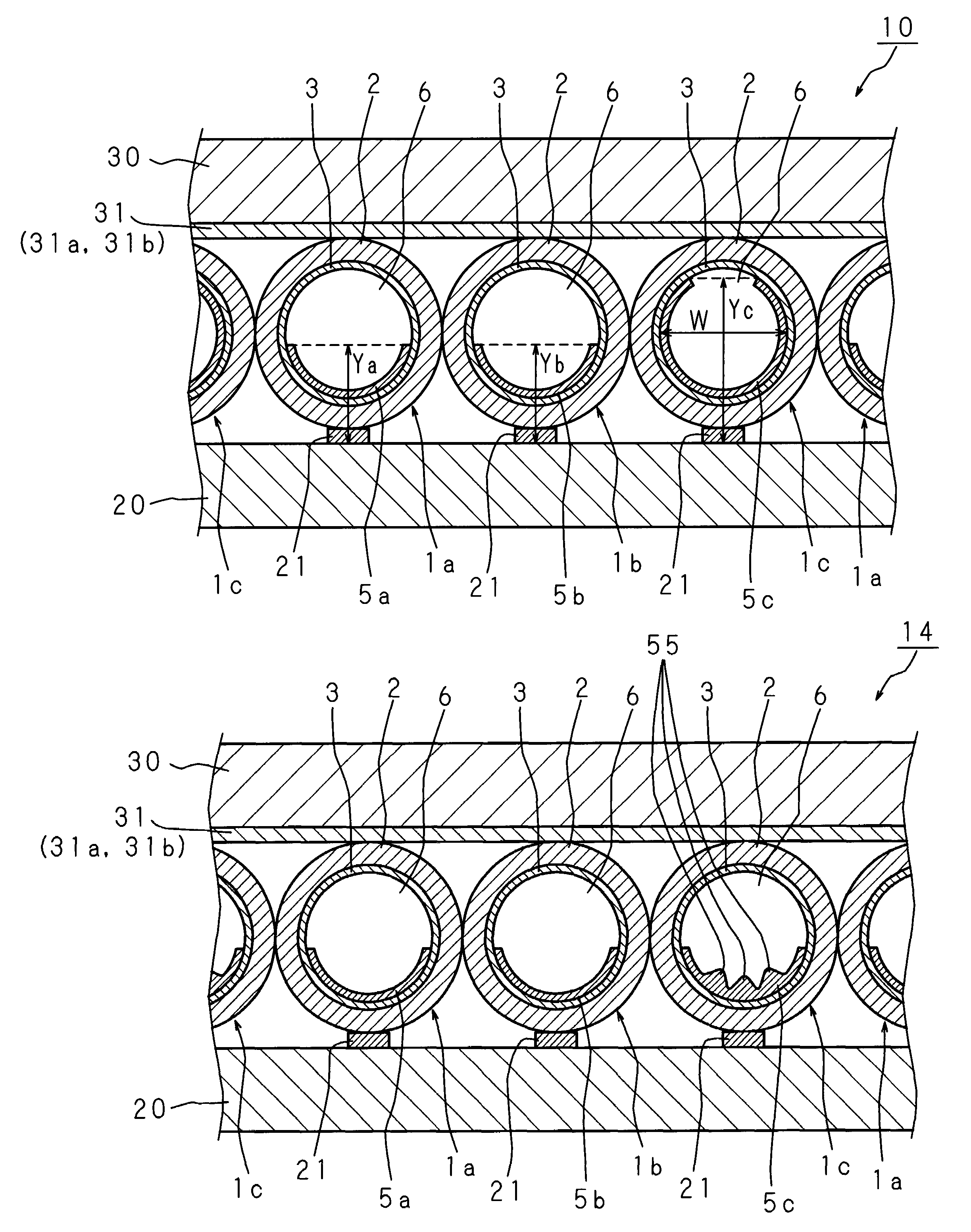
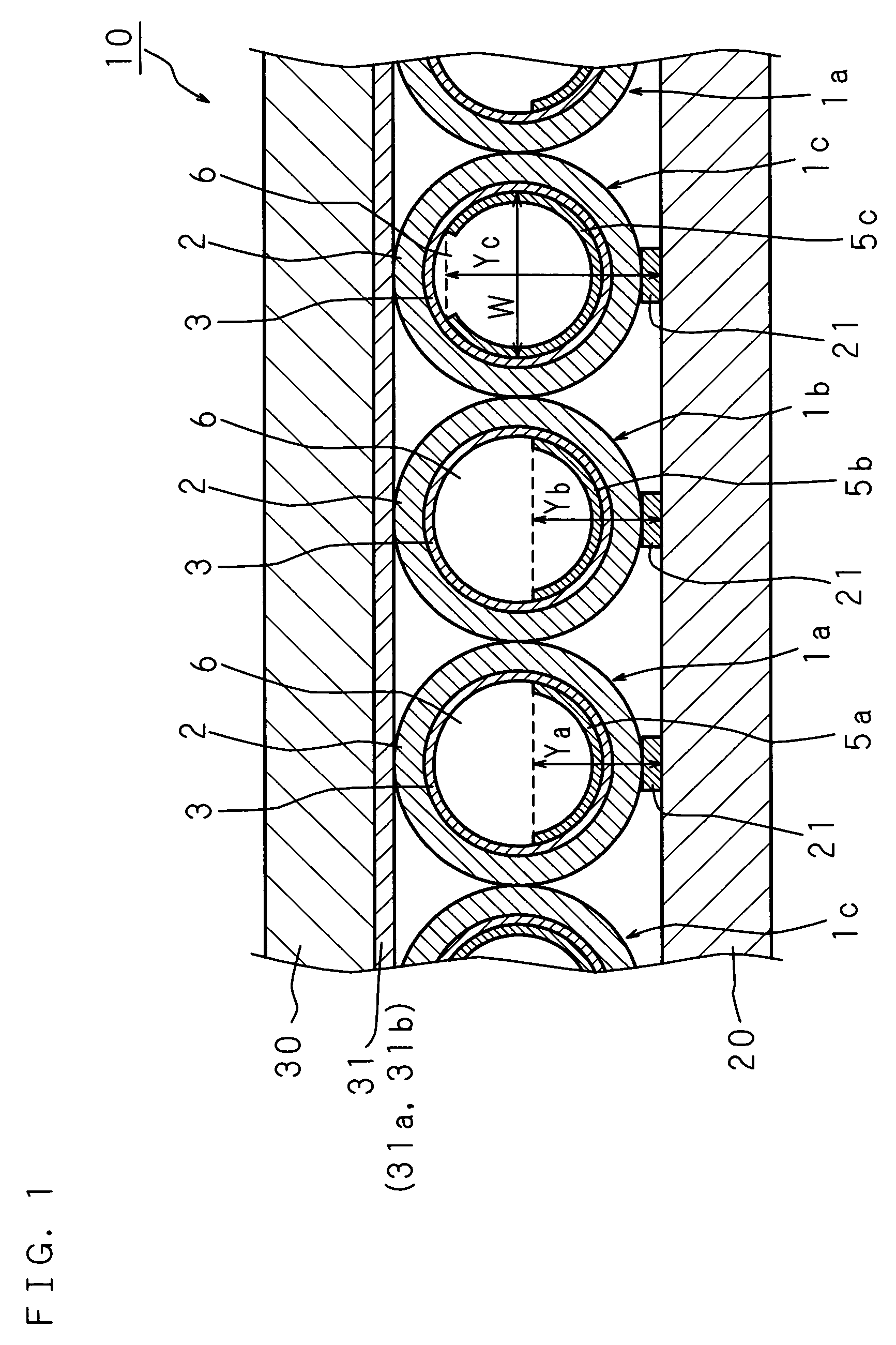
[0043]FIG. 1 is a structural cross sectional view showing one example of display device according to Embodiment 1 of the present invention. A display device 10 according to Embodiment 1 comprises a large number of red gas discharge tubes 1a, green gas discharge tubes 1b, and blue gas discharge tubes 1c (which may hereinafter be referred to as gas discharge tubes 1 if there is no need to distinguish them from each other), which are regularly arranged in a direction orthogonal to the axial direction thereof and sandwiched between a rear support body (substrate) 20 and a front support body (substrate) 30.

[0044]As the rear support body 20 and front support body 30, glass substrates are illustrated, but the rear support boy 20 and front support body 30 may also be made of flexible sheets such as polycarbonate films and PET (polyethylene terephthalate) films having light transmitting properties. In this case, it may be possible to deform the flexible sheets along the outer shape of gas di...

embodiment 2

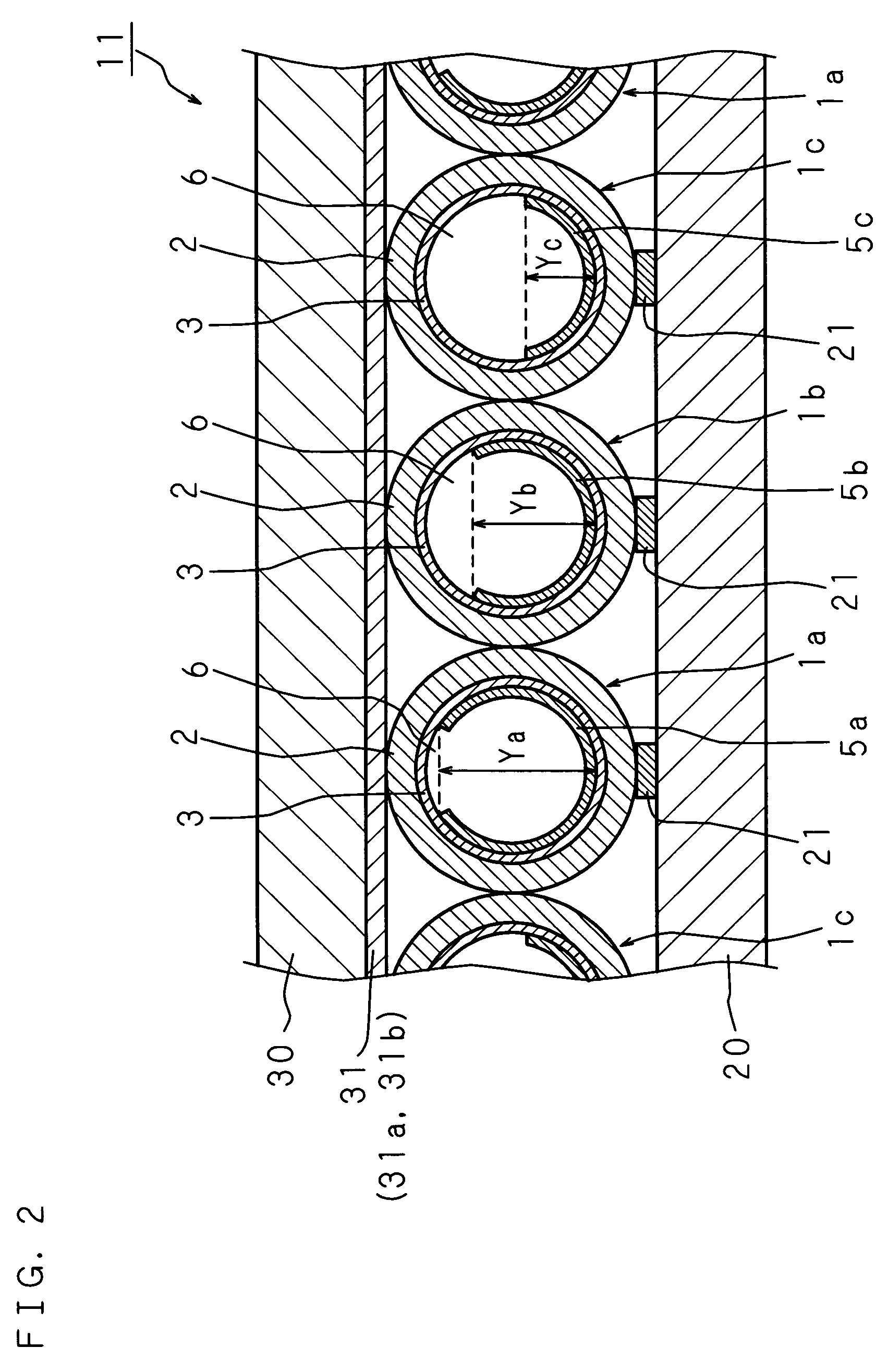
[0053]FIG. 3 is a structural cross sectional view showing one example of display device according to Embodiment 2 of the present invention. In a display device 12 according to Embodiment 2 of the present invention, the thickness Tc of the blue phosphor layer 5c is thicker than the thicknesses Ta and Tb of the red and green phosphor layers 5a, 5b, and establishes the relationship Tc>Ta=Tb. The widths of the phosphor layers 5a, 5b and 5c, which are the intervals in a radial direction of the respective red gas discharge tube 1a, green gas discharge tube 1c and blue gas discharge tube 1c, are substantially the same irrespective of the emission colors of the phosphor layers. Since other structures are the same as those in Embodiment 1, the corresponding parts are designated with the same codes, and the detailed explanation thereof is omitted.

[0054]Thus, by varying the thicknesses of the phosphor layers, the ultraviolet reflectance is increased. Consequently, the luminescence intensity of...

embodiment 3

[0057]FIG. 5 is a structural cross sectional view showing one example of display device according to Embodiment 3 of the present invention. In a display device 14 according to Embodiment 3 of the present invention, each of the red and green phosphor layers 5a and 5b has an axial cross section in the shape of a crescent moon. On the other hand, the axial cross section of the blue phosphor layer 5c has a shape composed of a plurality of projections and depressions arranged alternately like saw teeth. The widths of the phosphor layers 5a, 5b and 5c are substantially the same irrespective of the emission colors of the phosphor layers. Since other structures are the same as those in Embodiment 1, the corresponding parts are designated with the same codes, and the detailed explanation thereof is omitted.

[0058]Thus, the projecting sections 55 of the blue phosphor layer 5c are closer to the front support body 30, and the area irradiated with ultraviolet radiation becomes larger due to the p...


PUM


Abstract

A display device capable of realizing a desired color temperature is provided. Phosphor layers 5a, 5b and 5c, which are excited by ultraviolet radiation produced by discharge and emit red, green and blue visible light, are formed inside a red, green and blue gas discharge tube 1a, 1b, and 1c, respectively. The height Yc of the phosphor layer 5c with respect to a rear support body 20 is higher than the heights Ya and Yb of the phosphor layers 5a and 5b with respect to the rear support member 20, and establishes the relationship Yc>Ya=Yb. Therefore, the distance from the phosphor layer 5c to the opposite discharge surface on a front support body is shorter than those from the phosphor layers 5a and 5b, the visible light emitted from the display device 10 is shifted toward blue, that is, the color temperature increases.

Description

CROSS-REFERENCE TO RELATED APPLICATIONS[0001]This non-provisional application claims priority under 35 U.S.C. §119(a) on patent application Ser. No. 2004-240915 filed in Japan on Aug. 20, 2004, the entire contents of which are hereby incorporated by reference.BACKGROUND OF THE INVENTION[0002]The present invention relates to a display device capable of displaying images (video images) such as moving images by arranging a large number of thin gas discharge tubes with a discharge gas sealed therein.[0003]Plasma displays (PDP) are practically used as thin, large-screen next generation displays. In a PDP, discharge is caused in a very small closed space, and ultraviolet radiation (wavelength: 147 nm) emitted by the discharge excites a phosphor layer and is converted into visible light. A large display device using this light-emitting principle of PDP is proposed, which is capable of displaying video images such as moving images by arranging a large number of gas discharge tubes, each of ...

Claims


Application Information

Patent Timeline
Patent Type & Authority Patents(United States)
IPC IPC(8): H01J17/49H01J11/12H01J11/18H01J11/22H01J11/24H01J11/26H01J11/34H01J11/42H01J61/42H01J65/00
CPCH01J11/18H01J11/42
Inventor SHINOHE, KOJIISHIMOTO, MANABUAWAMOTO, KENJIYAMADA, HITOSHITOKAI, AKIRAYAMAZAKI, YOSUKEHIRAKAWA, HITOSHI
Owner SHINODA PLASMA
Why Eureka
Try Eureka