
Harness design supporting apparatus and method, and computer readable recording medium which stores harness design supporting program therein

a technology for supporting apparatus and harnesses, applied in the field of supporting harness design, can solve the problems of inability to verify the problem of harnesses relating to the motion of movable mechanical components, inability to realize verification, and inability to verify the effect of harness design, so as to improve the efficiency of harness design and increase the amount of processing.

Inactive Publication Date: 2009-01-20
FUJITSU LTD
View PDF7 Cites 14 Cited by
  • Summary
  • Abstract
  • Description
  • Claims
  • Application Information

AI Technical Summary

Benefits of technology

Enables real-time simulation and dynamic verification of harness motion, improving design efficiency by allowing designers to check for potential issues like interference and length problems, while reducing processing time and complexity.

Problems solved by technology

In reality, a harness is actually incorporated in a product prototype to adjust the length of the harness, so that problems related to the harness are not revealed quite a late stage.
However, since three-dimensional CAD data can only express static assembly conditions, the above systems cannot verify problems of harnesses relating to motion of movable mechanical components.
More specifically, the following problems are considerable in an apparatus in which a harness is incorporated.
At design of a harness, verification needs to be performed to check that the above problems do not occur, which verification cannot be realized in the above systems.
In addition, since harness models designed on a three-dimensional CAD are solid models, whose calculation is time-consuming, they present problems in operability.
In particular, in the above “EMbassy”, data written in VRML (Virtual Reality Modeling Language) is treated, and use of such data raises a problem of increasing display processing time.

Method used


Image

  • Harness design supporting apparatus and method, and computer readable recording medium which stores harness design supporting program therein
  • Harness design supporting apparatus and method, and computer readable recording medium which stores harness design supporting program therein
  • Harness design supporting apparatus and method, and computer readable recording medium which stores harness design supporting program therein

Examples


Embodiment Construction

)

[0029]One preferred embodiment of the present invention will now be described with reference to the relevant accompanying drawings.

[0030][1] Construction of a Harness Design Supporting Apparatus

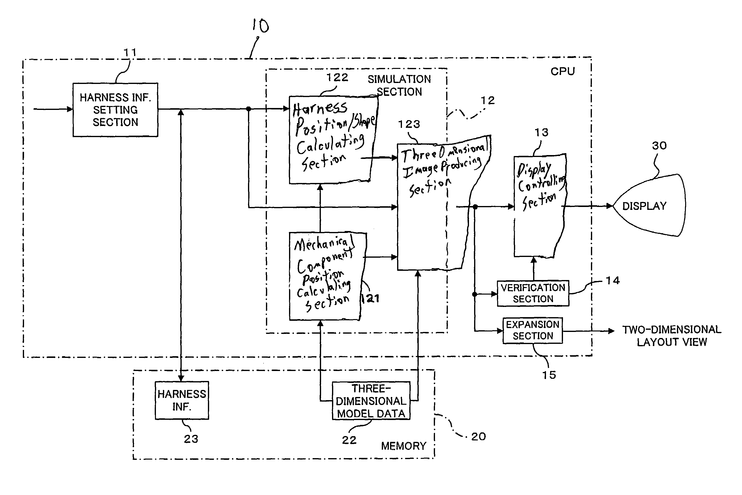
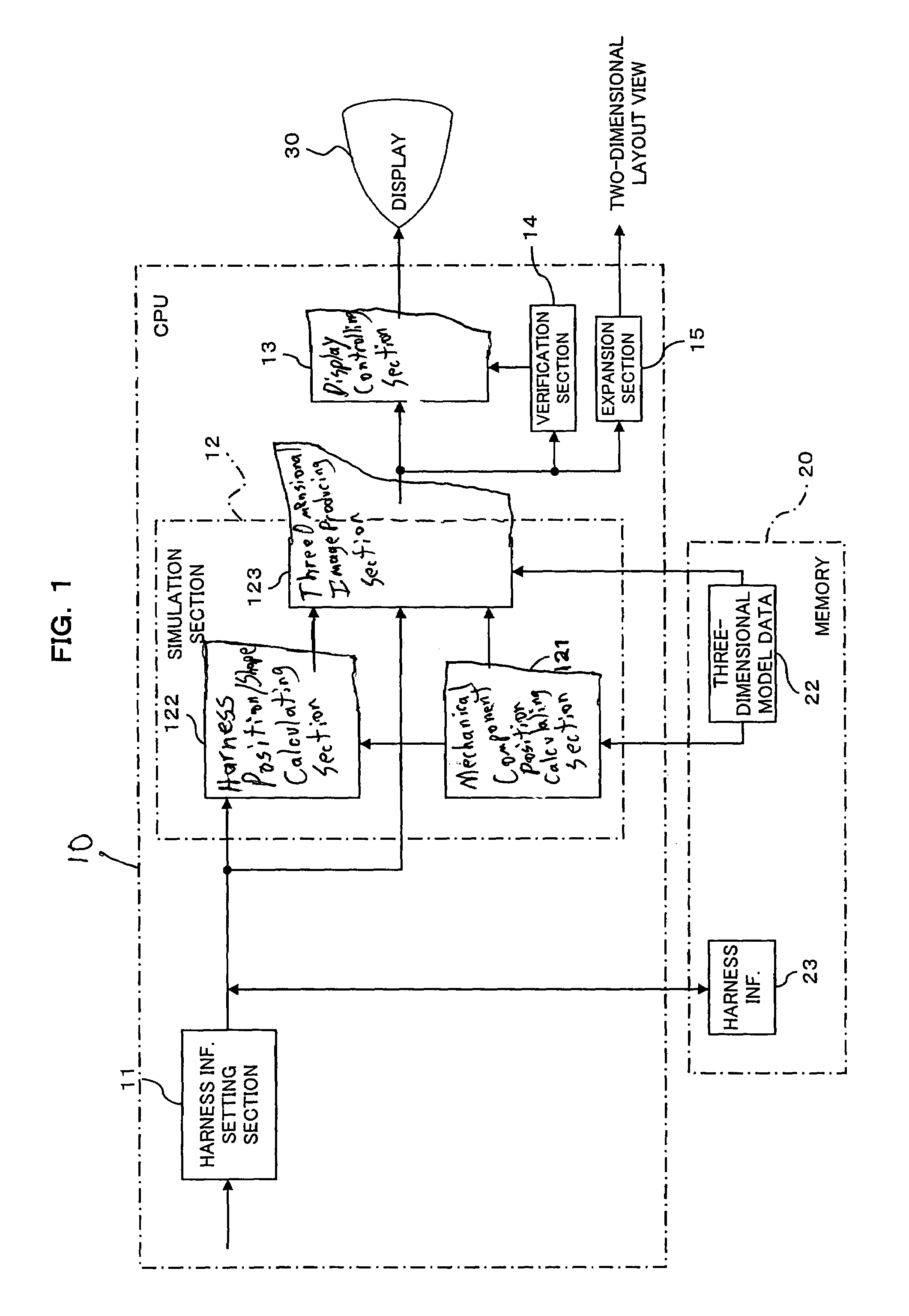
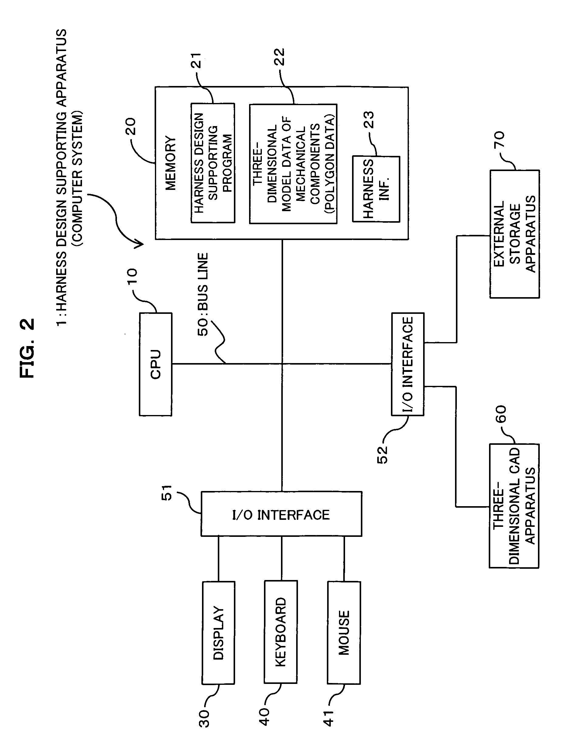
[0031]FIG. 1 is a block diagram showing a functional construction of a harness design supporting apparatus according to one preferred embodiment of the present invention; FIG. 2 is a block diagram showing a hardware construction of a computer system for realizing the harness design supporting apparatus of FIG. 1.

[0032]The computer system (for example, a personal computer) 1 of FIG. 1 and FIG. 2 of the present embodiment serves as an apparatus that supports placement design of a harness in an object apparatus (for example, a printer, an automobile, a machine tool, an industrial robot, and so on), in which a harness is to be incorporated.

[0033]Here, the “harness” includes flexible and pliable belt-like and line-like members and bundles of such members, such as wiring for supplying electric pow...


PUM


Abstract

The object is to provide an environment in which dynamic verification of harness design is available, and thereby realizing efficient harness design. The apparatus comprises: a mechanism information storing unit which stores in advance three-dimensional model data of a mechanical component, other than the harness, of the object apparatus; a harness information setting section which sets harness information; a simulation section which creates a three-dimensional mechanism model of the harness and of the mechanical component based on the harness information and on the three-dimensional model data of the mechanical component, and which simulates motion of the harness in conjunction with motion of the mechanical component using the three-dimensional mechanism model; a display; and a display controlling section which controls the display to show thereon the simulation result obtained by the simulation section.

Description

[0001]This application is a continuation application, filed under 35 USC 111(a), of International Application PCT / JP2002 / 009466, filed Sep. 13, 2002.BACKGROUND OF THE INVENTION[0002]1. Field of the Invention[0003]The present invention relates to technology for supporting design of a harness. The invention relates particularly to technology for realizing efficient harness design, such as installation position of a harness and design of a harness for its manufacturing, at designing and developing apparatus (for example, printers, automobiles, machine tools, industrial robots, and so on) in which a harness is incorporated. The “harness” in the present invention includes flexible and pliable belt-like and line-like members and bundles of such members, such as wiring incorporated in apparatus, cables, wires, piping and rubber hoses. The present invention is applied to placement design of such members.[0004]2. Description of the Related Art[0005]Generally speaking, when apparatus, such as...

Claims


Application Information

Patent Timeline
Patent Type & Authority Patents(United States)
IPC IPC(8): G06F17/50B60R16/02G06T17/10
CPCB60R16/0207G06F17/50G06F17/5009G06T17/10G06F2217/36Y02T10/82G06F2113/16G06F30/00G06F30/20G06F2119/18
Inventor HASHIMA, MASAYOSHISATO, YUICHI
Owner FUJITSU LTD
Learn More